
CT collision protection device and CT collision protection method thereof

A technology of collision protection and CT scanning, applied in the field of medical equipment, can solve the problems of infrared sensor doctor positioning interference, collision, high production cost, etc., and achieve the effects of real-time protection, accurate data, and accurate judgment

Pending Publication Date: 2020-08-28
SHINVA MEDICAL INSTR CO LTD
View PDF0 Cites 0 Cited by
  • Summary
  • Abstract
  • Description
  • Claims
  • Application Information

AI Technical Summary

Problems solved by technology

The former cannot solve the problem of collision between the CT frame cover and the lower end of the CT scanning bed when it is tilted, and the infrared sensor has interference with the doctor's positioning; while the latter can solve the problem of collision between the CT frame cover and the lower end of the CT scanning bed when it is tilted, However, the manufacturing cost of the resistive / capacitive CT scanning bed fixed cover and the CT frame cover is extremely high, often costing millions
[0004] In addition, there is also a collision protection method that uses software algorithms to detect the distance between the CT scanning table and the CT frame cover, but this method will introduce software calculation risks, and there is still a risk of collisions

Method used


Image

  • CT collision protection device and CT collision protection method thereof
  • CT collision protection device and CT collision protection method thereof
  • CT collision protection device and CT collision protection method thereof

Examples


Embodiment Construction

[0043] The following will clearly and completely describe the technical solutions in the embodiments of the present invention with reference to the accompanying drawings in the embodiments of the present invention. Obviously, the described embodiments are only some, not all, embodiments of the present invention. Based on the embodiments of the present invention, all other embodiments obtained by persons of ordinary skill in the art without making creative efforts belong to the protection scope of the present invention.

[0044]The core of the present invention is to provide a CT collision protection device, which can effectively prevent the CT scanning bed from colliding with the CT frame cover, and has a simple structure and low cost.

[0045] In addition, the present invention also provides a CT collision protection method applied to the above-mentioned CT collision protection device.

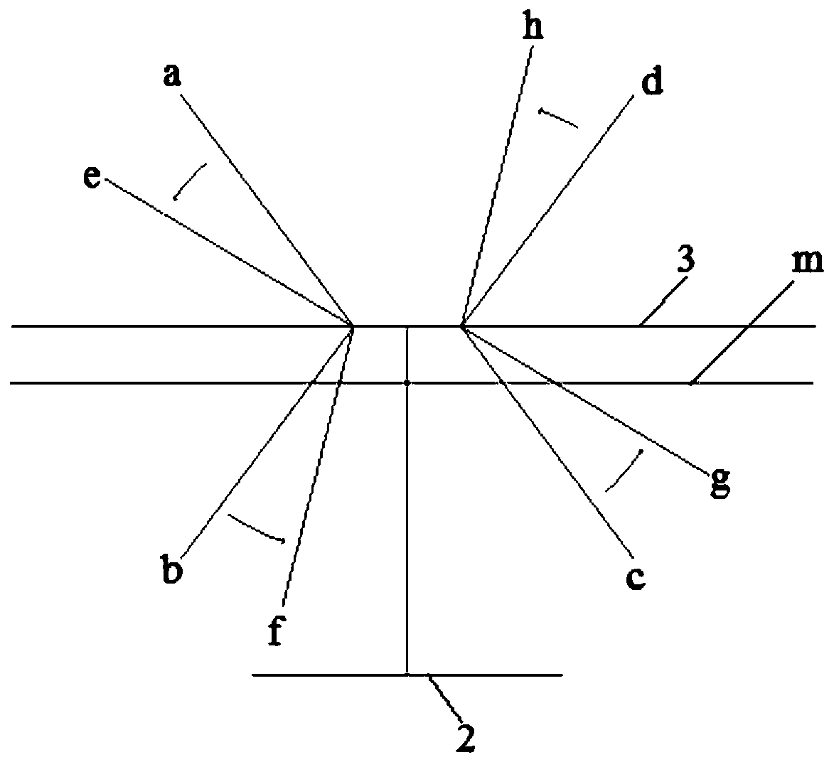
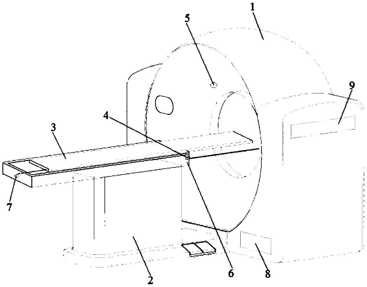
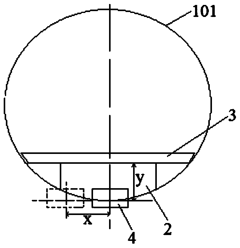
[0046] Please refer to Figure 1-Figure 7 , Simplified schematic diagram of the motion w...


PUM


Abstract

The invention discloses a CT collision protection device and a CT collision protection method thereof. The CT collision protection device comprises a collision distance sensor, an infrared induction sensor, a misoperation processing unit and a control feedback unit, wherein the collision distance sensor is vertically arranged on the end face, close to a CT rack housing, of a CT scanning bed body;when it is detected that the CT rack housing enters the safe distance of the CT scanning bed board, warning information is output; the infrared induction sensor is arranged at the upper end of the CTrack housing and outputs warning information after detecting that an examined patient leaves the safe area; the misoperation processing unit is used for outputting a collision signal when one of the CT scanning bed board and the CT rack housing moves; the control feedback unit is connected with a CT motion module; and the collision distance sensor, the infrared induction sensor and the misoperation processing unit are all connected with the control feedback unit, so that the CT motion module is controlled to stop moving when the warning information and the collision signal are received at thesame time, and collision between the CT scanning bed and the CT rack housing is effectively prevented.

Description

technical field [0001] The invention relates to the technical field of medical instruments, and more specifically, relates to a CT collision protection device. In addition, the present invention also relates to a CT collision protection method applied to the above-mentioned CT collision protection device. Background technique [0002] CT is widely used in the field of clinical medicine. During the scanning process, the CT scanning table can move forward and backward longitudinally and vertically, and the cover of the CT frame can tilt forward and backward. Because the motion relationship between the two is relatively complicated, the collision protection belt for CT Come to great challenge. [0003] Most of the collision protection in the prior art is to prevent the patient under examination from being squeezed, such as setting an infrared sensor to detect whether the patient under examination is squeezed; or using resistive materials and capacitive materials to make a fixe...

Claims


Application Information

Patent Timeline
IPC IPC(8): A61B6/10A61B6/03
CPCA61B6/035A61B6/102A61B6/105
Inventor 王学涛李志勇张志明李强强王笑宇于世忠
Owner SHINVA MEDICAL INSTR CO LTD
Learn More