Clinical emergency obstetric apparatus for obstetrics and gynecology department

A midwifery, obstetrics and gynecology technology, applied in medical science, surgery, vehicle rescue, etc., can solve problems such as infant head injury, infant injury, large traction, etc., to achieve firm fixation, avoid damage, and reduce damage. Effect

Active Publication Date: 2020-08-28
姚丽娟 +3
View PDF8 Cites 7 Cited by
  • Summary
  • Abstract
  • Description
  • Claims
  • Application Information

AI Technical Summary

Problems solved by technology

[0002] During delivery, pregnant women sometimes need to use forceps to fix the baby's head and pull the baby out slowly. However, in traditional forceps, the doctor applies force directly to the forceps. Due to the limited buffer, the force applied by the doctor can easily cause injury to the baby. , the doctor’s professional technical requirements are very high, but the existing clinical emergency midwifery devices still have the following problems; 1. When the midwifery device is pulled, the pulling force of the clip body cannot be monitored. When stuck, the excessive pulling force will cause damage to the baby's head; 2. The existing midwifery devices are all operated by the pregnant woman lying flat, which will require a large pulling force for the baby to be pulled out, which is not conducive to the smooth pulling of the baby ; 3, only the baby's head is pulled by the clip body, which not only makes the baby's head not firmly fixed, but also causes larger damage to the baby's head

Method used


Image

  • Clinical emergency obstetric apparatus for obstetrics and gynecology department
  • Clinical emergency obstetric apparatus for obstetrics and gynecology department
  • Clinical emergency obstetric apparatus for obstetrics and gynecology department

Examples


Embodiment 1

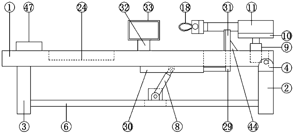
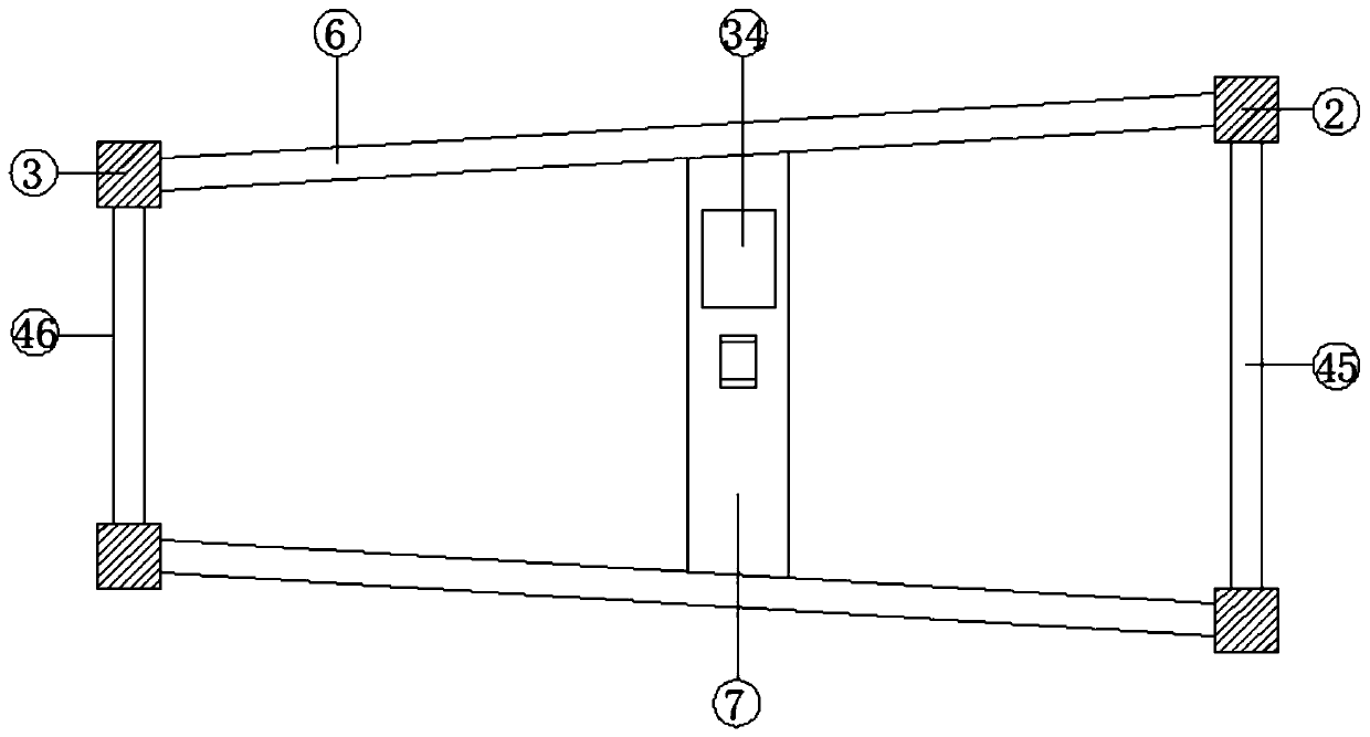
[0037] see Figure 1-9, a kind of obstetrics and gynecology clinical emergency obstetrical aid according to an embodiment of the present invention, comprising a bed board 1, first support columns 2 are provided under two corners of one end of the bed board 1, and two corners at the other end of the bed board 1 The second support column 3 is arranged under the corner, and the first installation plate 4 is fixed on the first support column 2. The middle part of the first installation plate 4 is provided with a perforation, and a rotating shaft is rotatably arranged in the perforation. 5. The rotating shaft 5 is fixedly connected to the outer walls on both sides of one end of the bed board 1 respectively, and the first reinforcing rib 6 is fixed between the first support column 2 and the second support column 3 on the same side, A second mounting plate 7 is fixed between the middle parts of the first reinforcing ribs 6, a hydraulic cylinder 8 is hinged on the middle part of the s...

Embodiment 2

[0040] see Figure 5 and 9 , for the connecting piece 19, the connecting piece 19 includes a first screw rod 35, one end of the first screw rod 35 is fixedly connected to the fixed plate 14, and the outer wall of the other end of the first screw rod 35 is threadedly connected with A threaded cylinder 36, the threaded cylinder 36 is internally threaded with a second screw 37 at one end away from the first screw 35, and the second screw 37 is fixedly connected with the sucker 20 at one end away from the threaded cylinder 36; For the first screw mandrel 35, a limit rope 38 is provided between the first screw mandrel 35 and the second screw mandrel 37, and one end of the limit rope 38 is fixedly connected to one end of the first screw mandrel 35 , the other end of the limiting rope 38 is fixedly connected with one end of the second screw rod 37 .

[0041] Through the above scheme of the present invention, the length that the first threaded mandrel 35 and the second threaded mand...

Embodiment 3

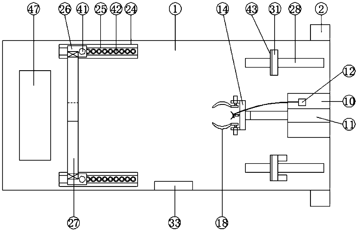
[0043] see Figure 5 , 7 And 8, for the suction cup 20, the suction cup 20 is connected with an air intake pipe 39, and the end of the air intake pipe 39 away from the suction cup 20 is equipped with a valve 40; for the locking device, the locking device includes a locking Bolts 41, threaded holes are provided on the slider 26, and locking bolts 41 are threaded in the threaded holes, and the upper surface of the sliding rod 25 is provided with a number of limiters that match the locking bolts 41. Bit slot 42.

[0044] Through the above scheme of the present invention, the valve 40 can be opened when the suction cup 20 is taken off from the baby's head, so that the outside air enters the suction cup 20 from the air intake pipe 39 and the suction cup 20 loses its suction force, thereby making it easy to take off the suction cup 20, and can pass Screw the locking bolt 41 into the limiting groove 42 to fix the slider 26 .


PUM


Abstract

The invention discloses a clinical emergency obstetric apparatus for a obstetrics and gynecology department. The clinical emergency obstetric apparatus comprises a bed board; first supporting columnsare arranged below the two corners of one end of the bed board; second supporting columns are arranged below the two corners of the other end of the bed board; first mounting plates are fixedly arranged on the first supporting columns; through holes are formed in the middles of the first mounting plates; rotating shafts are rotatably arranged in the through holes; and the rotating shafts are fixedly connected with the outer walls of the two sides of one end of the bed board respectively. The clinical emergency obstetric apparatus has the beneficial effects that pulling force of a clamp body can be detected in real time, so that the pulling force can be prevented from being continuously applied to the clamp body when a baby is stuck, and the head of the baby can be prevented from being injured due to overlarge pulling force; the bed board and a pregnant woman can be inclined, so that the baby can be pulled out more easily under the action of gravity; and the head of the baby can be adsorbed and fixed through a suction cup, so that the head of the baby can be fixed more firmly, and damage of the clamp body to the head of the baby can be reduced.

Description

technical field [0001] The invention relates to the field of medical equipment, in particular to an obstetrics and gynecology clinical emergency midwifery device. Background technique [0002] During delivery, pregnant women sometimes need to use forceps to fix the baby's head and pull the baby out slowly. However, in traditional forceps, the doctor applies force directly to the forceps. Due to the limited buffer, the force applied by the doctor can easily cause injury to the baby. , the doctor’s professional technical requirements are very high, but the existing clinical emergency midwifery devices still have the following problems; 1. When the midwifery device is pulled, the pulling force of the clip body cannot be monitored. When stuck, the excessive pulling force will cause damage to the baby's head; 2. The existing midwifery devices are all operated by the pregnant woman lying flat, which will require a large pulling force for the baby to be pulled out, which is not con...

Claims


Application Information

Patent Timeline
Patent Type & Authority Applications(China)
IPC IPC(8): A61G13/04A61G13/10A61G13/12
CPCA61G13/0009A61G13/04A61G13/10A61G13/1215A61G13/125A61G13/126A61G2200/12A61G2203/32A61G2203/34
Inventor 李庚阳
Owner 姚丽娟
Why Eureka
Try Eureka