Riveting tool

A riveting tooling and riveting technology, applied in the field of riveting tooling, can solve the problems of high labor costs, increased parts costs, and low production efficiency, and achieve the effects of reducing product costs, saving energy consumption, and improving processing efficiency

Pending Publication Date: 2020-08-28
广西贵港和乐门业有限公司
View PDF0 Cites 1 Cited by
  • Summary
  • Abstract
  • Description
  • Claims
  • Application Information

AI Technical Summary

Problems solved by technology

[0003] There are low production efficiency and high labor costs, resulting in increased parts costs

Method used


Image

  • Riveting tool
  • Riveting tool
  • Riveting tool

Examples


Embodiment 1

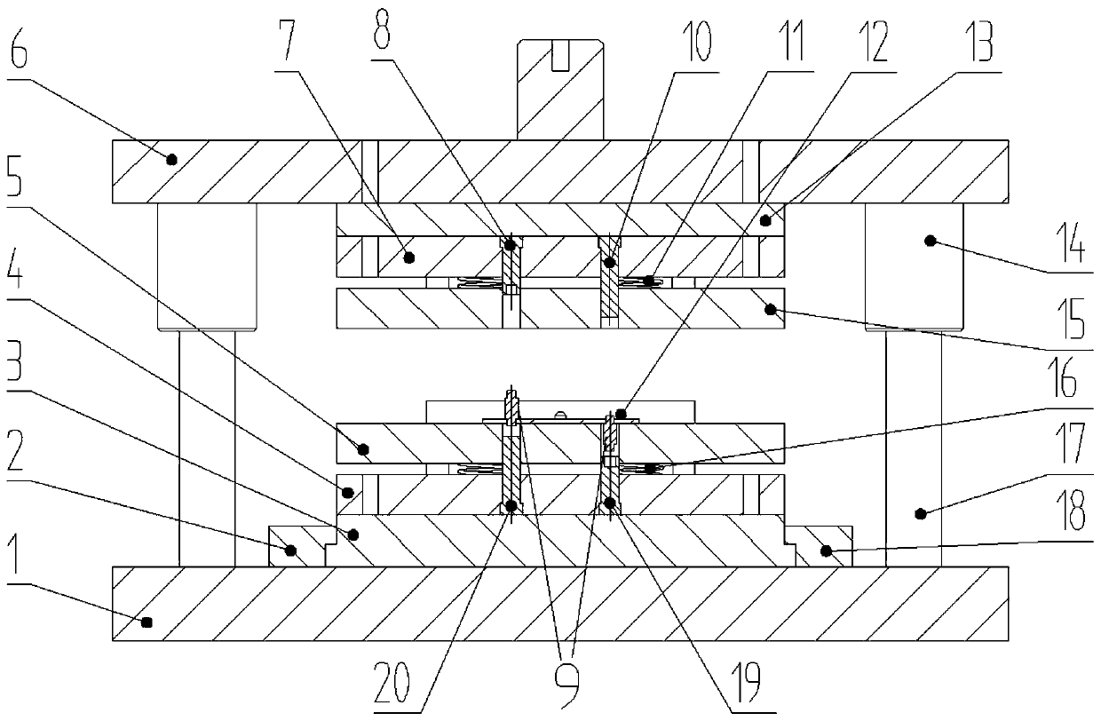
[0027] Such as figure 2 As shown, a riveting tool includes an upper template 6 and a lower template 1, including: an upper punch assembly, and the upper punch assembly includes a first upper punch 8 and a second upper punch installed on the upper template 6. Punch 10; upper stripping plate 15, two first through holes are provided on the upper stripping plate 15, and the first upper punch 8 and the second upper punch 10 are respectively arranged on the two first through holes. In the hole; the upper spring 11 is used to connect the upper stripping plate 15 to the upper template 6; the first upper punch 8 and the second upper punch 10 are all in the upper In the first through hole of the stripper plate 15.

[0028] The lower punch assembly, the lower punch assembly includes a first lower punch 19 and a second lower punch 20 installed on the lower template 1; the first lower punch 19 and the first upper punch 8 Cooperate, the second lower punch 20 and the second upper punch 10...

Embodiment 2

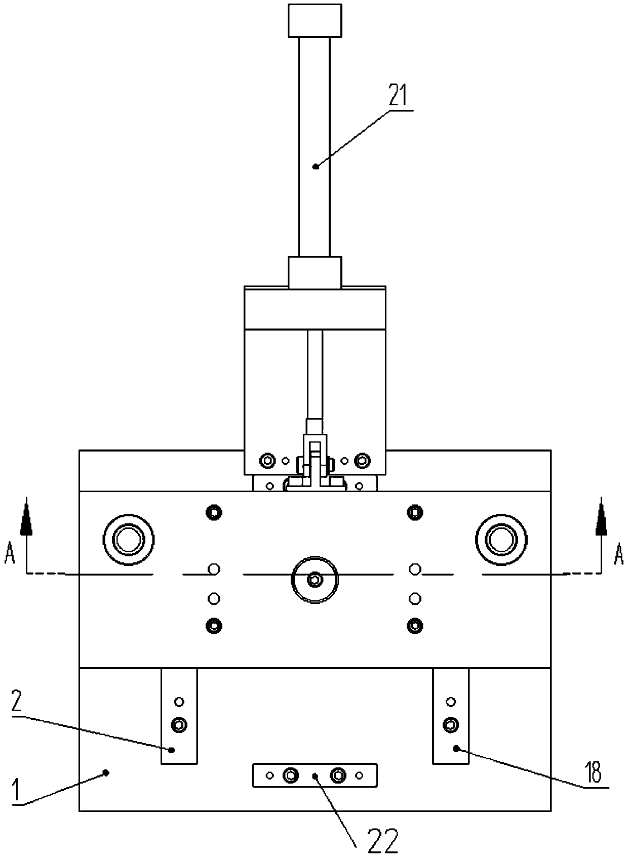
[0037] Such as figure 1 As shown, this implementation is further optimized on the basis of Embodiment 1. This embodiment focuses on the improvements compared with Embodiment 1, and the similarities will not be repeated. In this embodiment, the riveting tooling is also Including: a power assembly, the power assembly includes:

[0038] The lower die backing plate 3, the lower die backing plate 3 is slidably connected on the lower template 1, the lower punch assembly is fixed on the lower die backing plate 3, and the lower stripping plate 5 passes through the lower spring 16 is connected to the lower mold backing plate 3; power unit 21, the power unit 21 is connected to the lower mold backing plate 3; used to drive the lower mold backing plate 3 to reciprocate on the lower template 1 sports.

[0039] The power assembly is added, so that the lower mold backing plate 3 can be pushed out through the power device 21, so that the lower mold backing plate 3 moves together with the lo...

Embodiment 3

[0045] Such as figure 2 As shown, this implementation is further optimized on the basis of Embodiment 2. This embodiment focuses on the improvements compared with Embodiment 2, and the similarities will not be repeated. In this embodiment, the upper template 6 Upper die backing plate 13 is connected, and upper die backing plate 13 is connected with upper die punch fixing plate 7, and upper die punch fixing plate 7 is used for fixing the first upper punch 8 and the second upper punch 10; like this The advantage is that the first upper punch 8 and the second upper punch 10 can be fixed by steps, which is convenient for replacement and maintenance of the first upper punch 8 and the second upper punch 10 . In this structure, the upper stripping plate 15 is fixed on the upper die punch fixing plate 7 through the upper spring 11 .

[0046] A lower die punch fixing plate 4 is also arranged between the lower stripping plate 5 and the lower die backing plate 3, and the lower die punc...


PUM


Abstract

The invention discloses a riveting tool, and belongs to the technical field of riveting tools. The riveting tool comprises an upper punch assembly, an upper stripper plate, an upper spring, a lower punch assembly, a lower stripper plate and a lower spring, wherein the upper punch assembly comprises a first upper punch and a second upper punch which are arranged on an upper die plate; two first through holes are formed in the upper stripper plate; the first upper punch and the second upper punch are correspondingly arranged in the two first through holes respectively; the upper spring is used for connecting the upper stripper plate to the upper die plate; the lower punch assembly comprises a first lower punch and a second lower punch which are mounted on a lower die plate; two second through holes are formed in the lower stripper plate; the first lower punch and the second lower punch are correspondingly arranged in the two second through holes respectively; and the lower spring is usedfor connecting the lower stripper plate to the lower die plate. The tool can rivet rivets on the front face and the back face at a time, so that manual machining procedures are reduced; machining efficiency is improved; energy consumption is reduced; product cost is reduced; and market competitiveness is improved.

Description

technical field [0001] The invention relates to the technical field of riveting tooling, in particular to a riveting tooling. Background technique [0002] At present, the rivets on the parts (bolt fixing plate) inside the door lock can only be riveted in one direction at a time in the industry. For the front and back rivets that exist in the structure, the usual practice is to rivet the rivets on one side. Turn over and rivet the other side. [0003] There are low production efficiency and high labor costs, resulting in increased parts costs. Contents of the invention [0004] The purpose of the present invention is to provide a riveting tool in order to solve the technical problems in the background art. [0005] In order to achieve the above object, the present invention adopts the following technical solutions: [0006] A riveting tool, comprising an upper template and a lower template, including: an upper punch assembly, the upper punch assembly includes a first up...

Claims


Application Information

Patent Timeline
Patent Type & Authority Applications(China)
IPC IPC(8): B21J15/14
CPCB21J15/14
Inventor 吴泽军
Owner 广西贵港和乐门业有限公司
Why Eureka
Try Eureka