Automatic unhooking equipment for train rollover line and loaded line thereof
A technology for trains and heavy vehicles, which is applied to railway car body components, railway vehicle coupling accessories, railway couplings, etc., and can solve the problems of automatic decoupling of train overturning lines and heavy vehicles.
Inactive Publication Date: 2020-08-28
攀钢集团西昌钢钒有限公司
9 Cites 0 Cited by
AI-Extracted Technical Summary
Problems solved by technology
[0004] In view of this, the first object of the present invention is to provide an automatic unhooking device for the heavy train line of the train overturning line. Hook prob...
Method used
In the automatic decoupling equipment of the heavy vehicle line of the train overturning line, when in use, it is installed on the decoupling work position 2 of the heavy vehicle line, when the front compartment 1 of the heavy vehicle group moves to the decoupling work At this time, based on the recognition result of the recognition device 11, the controller controls the multi-dimensional drive device 5 to drive the special gripper 4 to move to complete the special gripper 4 moving to the unhooking handle, grasping the unhooking handle and moving to drive the unhooking The handle unhook operation, and then automatically complete the unhook operation. In the automatic unhooking equipment for the heavy train line on the overturning line of the train, thro...
Abstract
The invention discloses automatic unhooking equipment for a heavy train line of a train rollover line, wherein the equipment comprises an identification device which is used for identifying the position of an unhooking handle; a special gripper which is used for applying driving force to the unhooking handle; a multi-dimensional driving device which is used for driving the special gripper to moveto the unhooking handle and used for driving the unhooking handle to move in the unlocking direction so as to complete unhooking operation; and a controller that can control the multi-dimensional driving device to drive the special gripper according to the position of the unhooking handle recognized by the recognition device, and drive the unhooking handle according to the preset unlocking actioncorresponding to the current unhooking in multiple preset unlocking actions so as to complete the unhooking operation. The automatic unhooking equipment for the heavy train line of the train turnoverline can achieve automatic unhooking of the heavy train line of the train turnover line. The invention further discloses a train rollover line comprising the automatic unhooking equipment for the train rollover line heavy train line robot.
Application Domain
Railway coupling accessoriesLoading/unloading
Technology Topic
Identification deviceRollover +3
Image
Examples
- Experimental program(1)
Example Embodiment
[0021] The embodiment of the invention discloses an automatic unhooking device for the heavy line of a train rollover line to effectively solve the problem that the heavy line of the train rollover line cannot be automatically unhooked.
[0022] The technical solutions in the embodiments of the present invention will be clearly and completely described below in conjunction with the accompanying drawings in the embodiments of the present invention. Obviously, the described embodiments are only a part of the embodiments of the present invention, rather than all the embodiments. Based on the embodiments of the present invention, all other embodiments obtained by those of ordinary skill in the art without creative work shall fall within the protection scope of the present invention.
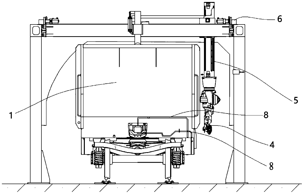
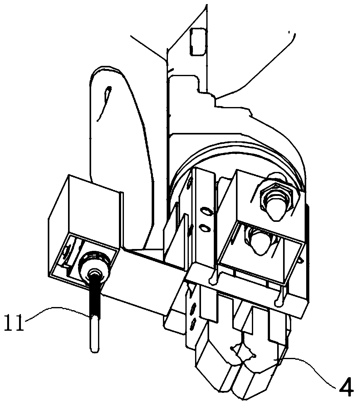
[0023] See Figure 1-Figure 4 , figure 1 It is a schematic diagram of the installation structure of the automatic unhooking device of the train rollover line heavy line robot provided by the embodiment of the present invention; figure 2 It is a schematic diagram of an end surface structure of an automatic unhooking device for a train rollover line heavy line robot provided by an embodiment of the present invention; image 3 It is a schematic structural diagram of a dedicated gripper provided by an embodiment of the present invention; Figure 4 It is a schematic diagram of the structure of the coupler position when the couplers of the two cars are disconnected.
[0024] In a specific embodiment, this embodiment provides an automatic decoupling device for the heavy carriage line of a train rollover line, which is mainly installed at the decoupling work position 2 of the heavy carriage line. Among them, the train group is mainly divided into a heavy train group and an empty train group. Each car of the heavy train group is a carriage loaded with goods, and each car of the empty train group is an empty carriage. For trains, the carriages are connected by a coupler 9, and the ends of the two carriages are rotatably connected with the coupler 9, and the hooks 10 of the two couplers 9 engage each other to achieve the hook connection. The hook tongue 10 is rotatably connected with the body of the coupler 9 and is provided with a locking member. When the locking member is locked, the hook tongues 10 that engage each other cannot be disengaged, but when the locking member is unhooked, even if the locking member When moving in the unlocking direction (unhooking direction), the hook tongues 10 engaged with each other can be separated. The coupler 13 and the carriages are rotatably connected around a vertical axis, so that the connected carriages are arranged in an arc.
[0025] The train rollover line mainly includes heavy and empty lines that are connected in sequence. On the heavy line, each car 1 is connected by a coupler and 9 hooks in turn to transmit power on the extension line of the track. When driving to the unhooking work position After 2, in the heavy vehicle group formed by each car 1 connected by the hook, the hook connection between the single car 1 at the foremost and the car 1 immediately after it is unhooked, that is, the unhooking member is driven Move according to the unhooking operation to drive the locking member into the unlocking position, so that the hook connection is unlocked, and the hook connection can be disengaged, and then push the unhooked single-carriage 1 into the dumper 3 of the dumper position, the dumper 3 Overturning the heavy vehicle to dump the internal cargo, that is, turning the open car 1 carrying a large amount of cargo over to tilt or invert it to dump the internal cargo, and then return to the normal position. At this time, the heavy truck becomes The empty car is then pushed out of the rollover space and then transported to the empty car line. In the empty car line, the newly entered single carriage 1 needs to move along the track to the empty car group, so that the connection end of the newly entered single carriage 1 enters the hook work position, and the car adjacent to the empty car group passes through the coupler 9 hook connection.
[0026] The unhooking member is a control device that controls whether the hook of the car coupler 9 is locked. In actual applications, the unhooking handle of the unhooking member is generally driven to move the unhooking handle in the unhooking direction to make the unhooking The hook piece completes the unhooking action, and then completes the unhooking operation. Different unhooking pieces need to complete different unlocking actions to realize the unhooking operation. These unhooking actions can be a single rotation operation or a single translation operation, or multiple identical or different actions are sequentially superimposed. Although there are many different types of unhooking elements, for the same type of unhooking elements, the unhooking operation is the same, and the types of unhooking elements are currently limited. The automatic unhooking equipment for heavy vehicle lines mainly includes an identification device 11, a special gripper 4, a multi-dimensional drive device 5 and a controller. To automatically complete the integrated unhooking operation from identifying the unhooking handle to operating the unhooking handle.
[0027] Specifically, the dedicated gripper 4 is used to apply driving force to the unhooking handle, and the multi-dimensional drive device 5 is used to drive the dedicated gripper 4 to move in a three-dimensional space, so that the multi-dimensional drive device 5 can drive the dedicated gripper 4 Move to the unhooking handle to connect with the unhooking handle, and then the multi-dimensional driving device 5 can drive the dedicated gripper 4 to move according to the predetermined moving steps to drive the unhooking handle to move according to the predetermined moving steps, and then complete the unhooking operation. The device formed by the combination of the dedicated gripper 4 and the multi-dimensional drive device 5 is generally a manipulator, and the multi-dimensional drive device 5 here is mainly used for refined operations.
[0028] It should be noted here that the dedicated gripper 4 exerts a driving force on the unhooking handle. It is not required that the dedicated gripper 4 and the unhooking handle can transmit driving forces in various directions, but at least it can be used to drive the unhooking handle. The driving force to move in the unlocking direction. Specifically, the general unhooking handle is rod-shaped, the unlocking action, the main movement includes radial movement and rotation around the non-centerline, where the non-centerline rotation means that the unhooking handle does not rotate around its own centerline. Instead, it rotates around an axis parallel to its own centerline and a certain distance apart, and the unhooking handle rotates along an arc at this time. When the unlocking action only includes radial movement and non-centerline rotation, of course, at this time, the dedicated gripper 4 can be clamped and fixed with the unhooking handle, such as a gripper, to transmit driving forces in various directions; it can also be a dedicated gripper. The hand 4 has a loop sleeved on the unhooking handle. Of course, the loop can also be a clamping ring. It is not clamped and fixed to the unhooking handle. It is only loosely sleeved on the unhooking handle so that it can be used in various diameters. The driving force in the direction shall prevail. The loop can drive the unhooking handle to move radially and non-centerline rotation, so as to ensure that even if the sleeve is connected, it can still drive the unhooking handle to move sequentially in the unlocking direction. The corresponding multi-dimensional driving device 5 should be able to drive the loop to be set in Unhook the handle. Specifically, the connection mode between the dedicated gripper 4 and the unhooking handle can be specifically defined according to the unlocking action requirements of the unhooking handle, and the unlocking action shall prevail, which is not specifically limited here.
[0029] The identification device 11 is mainly used to identify the position of the unhooking handle. The recognition device 11 can be a high-level intelligent means. The recognition device 11 can specifically adopt a machine vision system. The machine vision system converts the captured target into an image signal through a machine vision product, that is, an image capture device, and transmits it to a dedicated The image processing system obtains the shape information of the subject, and converts it into digital signals according to the pixel distribution, brightness, color and other information; the image system performs various operations on these signals to extract the characteristics of the target, and then obtains the position of the target. Of course, it can also be a general identification device 11. For example, the identification device 11 can include a touch switch for opposing the side wall of the car 1 or a distance detector for detecting the distance from the side wall of the car 1, and touch The switch will be empty bye and not touch the side wall of car 1, and then identify the end face of car 1, and the distance detector will not detect the side wall of car 1 because of the gap, and then recognize the end face of car 1, when it recognizes the end face of car 1 After that, it is possible to clarify the position of the end surface of one side car 1 in the extension direction of the track, and the relative positional relationship between the car 1 and the track is clear, and then according to the characteristics of the car 1, unhook the handle and the car 1 The position is clear, so that the positional relationship between the unhooking handle and the track can be clarified, and the position of the unhooking handle can be identified. Of course, considering that the unhooking handle generally extends horizontally, so that the unhooking handle has a certain tolerance space in the horizontal direction of the track, so the position of the unhooking handle in the horizontal direction of the track and the longitudinal direction of the track can be clarified. Based on this, it is only necessary to set the touch Touch the switch to identify the vertical position of the unhooking handle.
[0030] The controller is used to control the multi-dimensional drive device 5 to drive the special gripper 4 to move according to the position of the unhooking handle recognized by the identifying device 11 to complete the movement of the special gripper 4 to the unhooking handle, grasping the unhooking handle and moving The unlocking operation of the unhooking handle can be driven, and the multi-dimensional driving device 5 can be further controlled to drive the dedicated gripper 4 to reset. Specifically, the controller can control the multi-dimensional driving device 5 to drive the dedicated gripper 4 to move to the unhooking handle according to the position of the unhooking handle recognized by the identification device 11, that is, according to the identified unhooking handle position, make the special gripping The hand 4 moves closer to the unhooking handle. For example, using the current position of the special gripper 4 as the zero coordinate, the position of the unhooking grip is changed to three-dimensional coordinates through the identified position of the unhooking grip, and then the special gripper 4 is driven to move there. Three-dimensional coordinate position. Then the special gripper 4 is clamped or sleeved on the unhooking handle, and then the controller controls the multidimensional drive device 5 to drive the special gripper according to the predetermined unhooking action corresponding to the current unhooking member among the various preset unhooking actions. The hand 4 moves to drive the unhooking handle to complete the unhooking operation. It should be noted that how the controller selects the predetermined unlocking action corresponding to the current unhook from a variety of predetermined unlocking actions, can obtain the corresponding predetermined unlocking action according to the manual input selection instruction, or according to the identification device 11 or other detection Device detection to obtain the current unhook type. Among them, the recognition device 11 can recognize the hook by taking pictures and data analysis to obtain the general characteristics of the current hook, and then use the pre-stored several hook characteristics to identify which type of hook the current hook belongs to, and then select the corresponding Scheduled unlocking action.
[0031] In the automatic decoupling equipment for the heavy car line of the train rollover line, it is installed in the decoupling work position 2 of the heavy car line during application. When the front car 1 of the incoming heavy train group moves to the decoupling work position, At this time, based on the recognition result of the recognition device 11, the controller controls the multi-dimensional driving device 5 to drive the dedicated gripper 4 to move to complete the movement of the dedicated gripper 4 to the unhooking handle, grasping the unhooking handle and moving to drive the unhooking handle to unhook. Operation, and then automatically complete the unhook operation. In the automatic unhooking equipment for the heavy vehicle line of the train rollover line, the automatic unhooking operation is completed automatically through the special gripper 4, the identification device 11, the multi-dimensional driving device 5 and the controller, without manual operation. And a variety of predetermined unlocking actions corresponding to different types of unhooking parts are stored in the controller, so that different unlocking actions are adopted according to different unhooking parts, which fully guarantees the adaptability of the automatic unhooking equipment of the entire heavy vehicle line Therefore, the automatic unhooking equipment for the heavy vehicle line of the train rollover line can effectively solve the problem of insufficient automation of the unhooking of the heavy vehicle line of the train rollover line.
[0032] Further, considering that, in the heavy vehicle line, when the shunting machine 7 moves the first connection point of the heavy vehicle group to the unhooking work position 2, at this time the automatic unhooking device completes unhooking, and then the shunting machine 7 Push the uncoupled car 1 in the front section to pull the overturning space, and in the process of pulling the currently uncoupled heavy car to the overturning space, push out the empty car in the overturning space, and then the shunting machine 7 returns to the unhooking position, and after the unhooking is completed It usually takes a certain amount of time to return to the unhook position. In order to improve work efficiency, it is preferable to further include a transposition device 6 for driving the dedicated gripper 4 and the identification device 11 to move along the track, so that the dedicated gripper 4 can be driven from one end of the single carriage 1 to the other end, In application, the transposition device 6 can drive the special gripper 4 from the unhooking work position 2 and the identification device 11 to move one carriage 1 distance back from the unhooking work position 2, so that the automatic unhooking device is in the unhooking position After the unhooking is completed, the special gripper 4 and the identification device 11 are driven by the transposition device 6 to move to the connection point of the previous carriage, and then the unhooking handle is identified at this position to determine the position of the unhooking handle, and then the vehicle will be adjusted. 7 Return to the unhooking work position 2 to pull the first connection point of the subsequent heavy vehicle group, that is, the connection point where the unhooking handle is currently recognized by the identification device 11, and move one car forward 1 distance to enter the unhooking work Position 2, and then wait for the automatic decoupling device to complete the decoupling, and then the shunting machine 7 pulls the uncoupled heavy vehicle into the rollover bay and pushes out the empty vehicle in the rollover bay. While the above-mentioned shunting machine 7 pushes the uncoupling heavy vehicle into the overturning position to return to the unhooking work position 2, the identification device 11 moves backward by one carriage distance to complete the unhooking handle at the previous connection point Recognition.
[0033] Further, in order to operate more intelligently, here it is preferable that the identification device 11 can identify the type of the current unhooking handle. Specifically, as described above, the identification device 11 takes pictures through an electronic camera to obtain the unhooked photos, and transmits them to the controller for The device analyzes the characteristics of the unhooking structure of the image, matches with the pre-stored unhooking characteristics to obtain the unhooking type, and then controls to select the corresponding predetermined unlocking action according to the analyzed unhooking type. Among them, the controller analyzes the characteristics of the unhooking structure in the image, which is similar to the face recognition analysis technology. For unhooking, if only the upper and lower unhooks need to be distinguished, only the extension direction of the unhooking handle needs to be analyzed. Or you can distinguish different types of unhooking by the number of unhooking bending points.
[0034] The transposition driving device described above is used to drive the special gripper 4 and the identification device 11 to move. Specifically, for faster operation, it preferably includes a base, on which the special gripper 4, the identification device 11 and the multi-dimensional The driving device 5 and the transposition device 6 are used to drive the base from one end of the single carriage 1 to the other end, and a fixing device for fixed connection with the carriage 1 is provided on the base, so that the identification device 11 can identify the unhooking handle After the position, the base can be fixedly connected to the carriage 1 to better follow the carriage 1 to the unhooking work position 2 to ensure the relative positional relationship between the base and the carriage 1. The fixing device may be an electric clamping device, or an electromagnet, to generate a magnetic attraction when energized, so as to be adsorbed on the carriage 1.
[0035] In order to better improve work efficiency, it is preferable here that the transposition device 6 drives the base to move back from the unhooking work position 2 by a distance of the carriage 1, and after the identification device 11 recognizes the position of the unhooking handle connected to the hook , The controller controls the multi-dimensional drive device 5 on the base to drive the special gripper 4 to move to the unhooking handle connected to the current hook, and controls the multi-dimensional drive device 5 to drive the special gripper 4 to clamp the unhooking handle, and then wait for the shunting machine 7 Return to unhooking work position 2 to pull the heavy vehicle group to move forward by the length of carriage 1 so that the unhooking handle currently connected to the hook moves to unhooking work position 2, and then the controller controls the multidimensional driving device 5 to drive the unhooking handle to complete unlocking action.
[0036] Based on the automatic unhooking device for the train rollover line robot in the above embodiments, the present invention also provides a train rollover line. The train rollover line includes any one of the train rollover line automatic unhooking robots in the above embodiments. Unhooking equipment, the train rollover line also includes a shunting machine 7 set in the uncoupling position, and the shunting machine 7 is used to move the heavy vehicle group forward by a length of a single carriage 1, and is in the middle of the heavy vehicle group. After the vehicle in front is uncoupled, the vehicle in front of the heavy vehicle group is pulled into the rollover bay and the empty vehicle in the rollover bay is pushed out. Since the train rollover line adopts the automatic unhooking device of the train rollover line heavy line robot in the above embodiment, please refer to the above embodiment for the beneficial effects of the train rollover line.
[0037] The various embodiments in this specification are described in a progressive manner. Each embodiment focuses on the differences from other embodiments, and the same or similar parts between the various embodiments can be referred to each other.
[0038] The foregoing description of the disclosed embodiments enables those skilled in the art to implement or use the present invention. Various modifications to these embodiments will be obvious to those skilled in the art, and the general principles defined in this document can be implemented in other embodiments without departing from the spirit or scope of the present invention. Therefore, the present invention will not be limited to the embodiments shown in this text, but should conform to the widest scope consistent with the principles and novel features disclosed in this text.
PUM


Description & Claims & Application Information
We can also present the details of the Description, Claims and Application information to help users get a comprehensive understanding of the technical details of the patent, such as background art, summary of invention, brief description of drawings, description of embodiments, and other original content. On the other hand, users can also determine the specific scope of protection of the technology through the list of claims; as well as understand the changes in the life cycle of the technology with the presentation of the patent timeline. Login to view more.