[0058] By explaining the following preferred embodiments of the present application, other objects and advantages of the present invention will become clear.
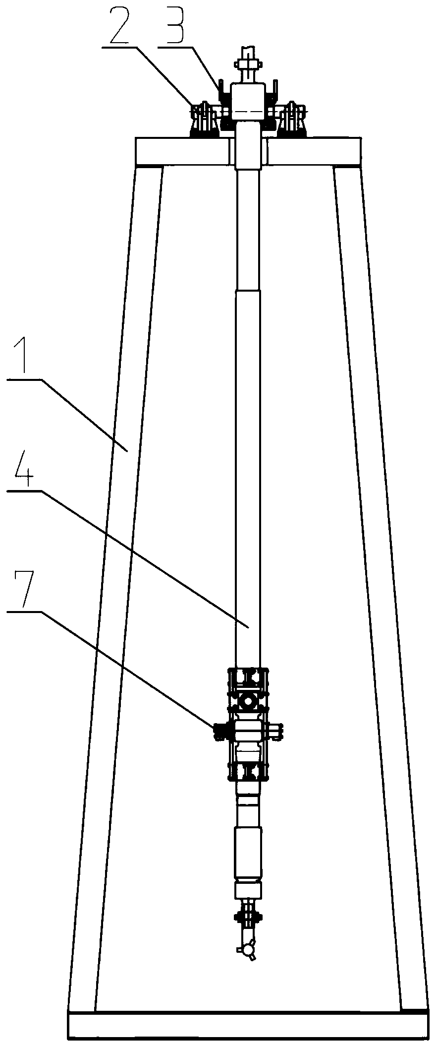
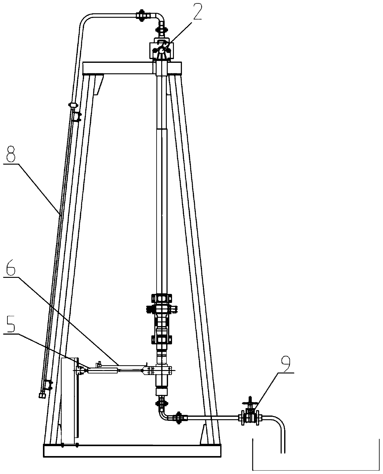
[0059] figure 1 It is a front view of a simulated drilling well deviation test equipment of the present invention. figure 2 for figure 1 Side view.
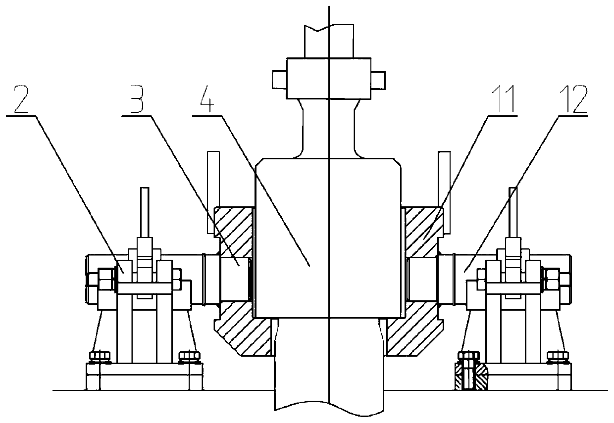
[0060] Such as figure 1 , figure 2 As shown, a simulated well deviation test equipment includes a main support 1, a push-pull device 5 and an angle measurement device 6. Wherein, the first end pin of the tool under test 4 is connected to the main support 1. One end of the push-pull device 5 is connected to the main support 1, and the other end is connected to the tool under test 4. The push-pull device 5 is used to push or pull the tested tool 4 to deflect the tested tool 4. The angle measuring device 6 is connected to the tool under test 4 and is used to measure the offset distance of the second end of the tool under test 4.
[0061] Specifically, the main support 1 is a vertical support, which can better simulate the actual working state of the tool 4 under test compared to a horizontal support, and has a smaller footprint. The main support 1 may be formed by welding profiles, for example, and the bottom of the main support 1 is fixedly connected to the ground. A ladder can be installed on the main support 1 to facilitate the operator to climb to the top of the main support 1 to install or remove the tool 4 under test.
[0062] The tool 4 to be tested may be, for example, a screw drilling tool, a vertical drilling tool, and other drilling tools used in the downhole.
[0063] The upper end of the tested tool 4 is hung on the main support 1. Specifically, the top end of the tested tool 4 is connected with the tool connection tool 3, the tool connection tool 3 is pin-connected with the suspension mechanism 2, and the suspension mechanism 2 is fixed on the top of the main bracket 1. Thus, the pin connection between the tool under test 4 and the main bracket 1 is realized. In the natural state, the tool 4 under test is in a vertical state.
[0064] When the tested tool 4 is a vertical drilling tool, a correction force measuring device 7 is also installed at the position corresponding to the pushing block of the vertical drilling tool. When the vertical drilling tool is tilted, the push block on the high side of the vertical tool extends outward to keep the vertical drilling tool in a vertical downward drilling direction. The correction force measuring device 7 is used to measure the correction force generated by the pushing block when the vertical drilling tool is inclined.
[0065] Such as figure 2 As shown, one end of the push-pull device 5 is connected to the main support 1, and the other end is connected to the tested tool 4. The push-pull device 5 is used to push or pull the tested tool 4 to make the tested tool 4 Skewed. The push-pull device 5 can be, for example, a hydraulic cylinder, an electric push rod, or the like. Since the upper end of the tested tool 4 is connected to the top of the main support 1 through the suspension mechanism 2, the push-pull device 5 can push the tested tool 4 to deflect. An angle measuring device 6 is also installed on the push-pull device 5, and the angle measuring device 6 is used to measure the offset distance of the lower end of the tool 4 under test.
[0066] In some embodiments, the test equipment further includes a circulation system 8 and a pressure holding device 9. The circulation system 8 is connected to the inflow end of the tool under test 4 and is used to deliver fluid to the tool under test 4. The pressure holding device 9 is connected to the outflow end of the tested tool 4 and is used to increase the fluid pressure at the outflow end of the tested tool 4. The aforementioned circulation system 8 may, for example, include a pump and a pipeline, and the outlet of the pump is connected to the inflow end of the tool under test 4 through the pipeline. The above-mentioned pump may be, for example, a mud pump or a plunger pump. The aforementioned pipeline may be a metal or non-metal pipeline, for example. The pressure holding device 9 may be, for example, a valve. When the pump is working, the pump injects fluid into the inflow end of the tool under test 4 through the pipeline. The system pressure is established at the outflow end of the tool 4 under test by adjusting the pressure holding device 9. For example, when the pressure holding device 9 is a valve, the above operation can be achieved by adjusting the opening of the valve.
[0067] image 3 It is a schematic structural diagram of a suspension mechanism 2 of the present invention. Figure 4 for image 3 Left view. Figure 5 for image 3 Top view.
[0068] Such as image 3 As shown, the top end of the tool 4 to be tested is hung in the main body 11 of the tool connection tool 3. A rotating shaft 12 extending in the horizontal direction is respectively provided on both sides of the tool body 11 of the tool connecting tool 3, and the two rotating shafts 12 are arranged coaxially and welded to the tool body 11 as a whole. The suspension mechanism 2 is fixed on the top of the main frame. The tool connection tool 3 is rotatably connected with the suspension mechanism 2 through the rotating shaft 12.
[0069] Such as Figure 4 As shown, the suspension mechanism 2 includes a suspension support 13, a suspension top cover 14 and a suspension pin 15. The suspension support 13 and the main support 1 can be fixedly connected by fasteners. The suspension top cover 14 and the suspension support 13 are rotatably connected by a suspension pin 15. The top of the suspension support 13 is provided with a semicircular groove, and the bottom of the suspension top cover 14 is also provided with a semicircular groove. The two semicircular grooves can be enclosed to form a circular hole. The above-mentioned circular hole is matched with the rotating shaft 12 of the tool connection tool 3 to realize a rotatable connection. Both the suspension top cover 14 and the suspension support 13 have a half-open bearing structure. When the suspension top cover 14 and the suspension support 13 are closed, the free ends of the two can be connected by a pin or bolt.
[0070] Such as Figure 5 As shown, a top platform 10 is provided on the top of the main support 1, and a U-shaped groove 101 extending in the horizontal direction with one end open is provided on the top platform 10. A suspension mechanism 2 is respectively arranged on both sides of the U-shaped groove 101, and the circular holes of the two suspension mechanisms 2 are arranged concentrically.
[0071] When installing the tool under test 4, first connect the tool connection tool 3 with the top end of the tool under test 4, and lift the upper end of the tool under test 4 through the lifting equipment and tool connection tool 3. The tool under test 4 is lifted from the U-shaped groove 101 The open end enters into the U-shaped groove 101. Put the two rotating shafts 12 of the tool connection tool 3 into the semicircular groove of the suspension support 13, and cover the suspension top cover 14 on the suspension support 13, and connect the suspension top cover 14 and the suspension through the pin The support 13 is connected.
[0072] Image 6 It is a schematic structural diagram of a push-pull device 5 of the present invention. Figure 7 for Image 6 Top view.
[0073] Such as Image 6 As shown, the push-pull device 5 includes a tool fixing card 16, a hydraulic cylinder 18, a cylinder seat 19, and a cylinder support frame 20. The tool fixing card 16 is detachably connected to the tested tool 4, and the tool fixing card 16 is connected to the tested tool 4 before the test. The tool 4 is fixedly connected, and the tool fixing card 16 is separated from the tool 4 under test after the test is completed. One end of the hydraulic cylinder 18 is connected with the tool fixing card 16 through a fixed pin 17, and the other end of the hydraulic cylinder 18 is connected with the cylinder seat 19 through a fixed pin 17. The cylinder base 19 is connected to the main support 1 through the cylinder support frame 20.
[0074] Such as Figure 7 As shown, the cylinder seat 19 and the cylinder support frame 20 can be slidably connected up and down, and the height position of the hydraulic cylinder 18 can be adjusted as required. In this embodiment, the cylinder support frame 20 is provided with a track extending in the vertical direction, and the cylinder block 19 is provided with a groove body matching the track. The cylinder block 19 is connected to the cylinder support frame by a T-bolt 22 20 connections.
[0075] In this embodiment, the angle measuring device 6 includes a displacement sensor used to measure the extension change of the piston rod of the hydraulic oil cylinder. Specifically, one end of the displacement sensor is connected with the cylinder barrel of the hydraulic cylinder 18, and the other end is connected with the piston rod of the hydraulic cylinder 18, so that the displacement sensor can acquire the extension change of the piston rod of the hydraulic cylinder 18. Preferably, the above-mentioned displacement sensor is a rope displacement sensor 21.
[0076] When the tool under test 4 is a vertical drilling tool, a pushing block is installed on the vertical drilling tool. When the vertical drilling tool is tilted, the pushing block on the high side of the vertical drilling tool extends and leans against the well wall, inside the vertical drilling tool. The circulating liquid gives the pushing block a hydraulic pressure, so that the pushing block is pressed against the well wall, and the tool is centered by the reaction force of the well wall. The maximum extension of the pushing block is about 10mm.
[0077] Figure 8 It is a schematic diagram of the installation structure of a correction force measuring device 7 of the present invention. Picture 9 for Figure 8 A-A section view in. Picture 10 for Figure 8 Section B-B in the.
[0078] Such as Figure 8 with Picture 9 As shown, when the tool under test 4 is a vertical drilling tool, the present invention may also include a correction force measuring device 7, which is used to measure the tool under test 4 at different deflection angles. The corrective force. The correction force measuring device 7 includes a force measuring unit 23, a first mounting plate 24, a second mounting plate 25 and a mounting frame 26.
[0079] The mounting frame 26 includes a first frame body and a second frame body, the first frame body and the second frame body are symmetrically arranged, and the first frame body and the second frame body can be installed to the tool under test 4 by fasteners such as bolts. The first mounting plate 24 and the second mounting plate 25 are fixedly connected to the mounting frame 26. The first mounting plate 24 and the second mounting plate 25 are symmetrically arranged on both sides of the mounting frame 26. The two force measuring units 23 are respectively fixedly connected to the first mounting plate 24 or the second mounting plate 25.
[0080] Such as Picture 10 As shown, in order to improve the bearing capacity of the correction force measuring device 7 at the force measurement point, it also includes a connecting bolt 27 and a bolt fixing sleeve 28. One end of the connecting bolt 27 is connected to the first mounting plate 24 and the other end is connected to the second mounting plate 25 . The bolt fixing sleeve 28 is sleeved on the connecting bolt 27, and one end of the bolt fixing sleeve 28 abuts against the first mounting plate 24 and the other end abuts against the second mounting plate 25. Based on the above structure, the connecting bolt 27 can bear the thrust of the pushing block, which has a high bearing capacity; in addition, the above structure is also convenient for installation and disassembly.
[0081] Picture 11 It is a structural schematic diagram of a force measuring unit 23 of the present invention.
[0082] Such as Picture 11 As shown, the force measurement unit 23 includes a sensor bracket 33 and a force measurement sensor 37. The sensor bracket 33 is connected to the first mounting board 24 or the second mounting board 25, the load cell 37 is installed inside the sensor bracket 33, and the load cell 37 is used to measure the thrust of the pushing block of the tool 4 under test.
[0083] Furthermore, the force measurement unit 23 further includes a top wire 29, a force measurement module 30, a disc spring 31, a sensor mounting plate 35 and an adjustment screw 39. Specifically, the sensor bracket 33 is provided with an accommodating space, one end of the sensor bracket 33 is fixed with a guide sleeve 32 and the other end is fixed with a rear cover 40. The guide sleeve 32 and the rear cover 40 are respectively connected with the sensor bracket 33 by fasteners. The force measuring module 30 and the sensor mounting plate 35 are located in the containing space, and are slidably connected to the sensor bracket 33. The disc spring 31 is located between the force measuring module 30 and the sensor mounting plate 35, one end of the disc spring 31 abuts against the force measuring module 30, and the other end of the disc spring 31 abuts against the sensor mounting plate 35. The front end of the top wire 29 is located outside the sensor bracket 33, and the rear end passes through the force measurement module 30, the disc spring 31 and the sensor mounting plate 35 in sequence, and is connected with the force measurement nut 36. The tip of the top wire 29 has a protruding portion with a larger diameter, and the protruding portion abuts against the front end surface of the force measurement module 30. Thus, the top wire 29 connects the force measurement module 30, the disc spring 31 and the sensor mounting plate 35 into one body. The force measuring module 30 and the guide sleeve 32 are slidably connected. It should be noted that the front end (protrusion) of the top wire 29 refers to the end of the top wire 29 close to the tool under test 4, and the rear end is the end far away from the tool under test 4.
[0084] The adjusting screw 39 is threadedly connected with the load cell 37, and the rear end of the adjusting screw 39 passes through the rear cover 40 and extends to the outside of the sensor bracket 33. The adjusting screw 39 is rotatably connected with the rear cover 40. Preferably, a thrust bearing 38 is provided between the adjusting screw 39 and the rear cover 40. By rotating the adjusting screw 39, the load cell 37 can be pushed or pulled to move the load cell 37 along the central axis OO', thereby adjusting the protruding length of the front end of the top screw 29 in a natural state, and adapting to the test requirements of the tool 4 under test.
[0085] A guide key 34 is also fixed on the outer contour of the force measuring module 30 and the outer contour of the sensor mounting plate 35. The guide key 34 can reduce the distance between the force measuring module 30 and the sensor bracket 33, or the sensor mounting plate 35 and the sensor bracket 33. Friction between.
[0086] When the tested tool 4 is in a vertical state, there is a gap of 2 to 3 mm between the pushing block on the tested tool 4 and the front end surface of the top wire 29. When the tool under test 4 deviates from the vertical state, the pushing block on the tool under test 4 extends outward along the radial direction of the tool under test 4, and the maximum extension is about 10mm. The disc spring 31 is used to compensate for this extension. 出量.
[0087] In some embodiments, the simulated well deviation testing equipment further includes a control unit, which is respectively connected to the push-pull device 5 and the angle measurement device 6 for calculating the tool under test according to the offset distance 4, and control the push-pull device 5 to push or pull the second end of the tool under test 4 so that the deflection angle reaches a set deflection angle.
[0088] Such as Picture 12 As shown, a drilling tool test method mainly includes the following steps:
[0089] S10. Suspend and pivotally connect the first end of the tool 4 under test to the main support 1. Generally speaking, hoisting equipment, such as cranes, cranes, etc., can be used to hoist the first end of the tool under test 4, and the first end is the upper end of the tool under test 4 when it is used for drilling operations.
[0090] S20: Push or pull the second end of the tool under test 4 to deflect the tool under test 4. For example, the push-pull device 5 can be used to push and pull the second end of the tool under test 4, which is the lower end of the tool under test 4 when it is used for drilling operations. Since the first end of the tool under test 4 is suspended and pivotally connected to the top of the main support 1, the second end can rotate at a certain angle with the pivot point as the axis when being pushed/pulled.
[0091] S30. Measure the offset distance of the second end of the tool 4 under test.
[0092] Such as Figure 13 As shown, the offset distance of the second end of the tested tool 4 is X. When the deflection angle of the tested tool 4 is small, the following formula can be used to approximate the offset distance X:
[0093] X=B-A
[0094] Among them, X is the offset distance of the second end; A is the original length of the push-pull device 5; B is the length of the push-pull device 5 after the tool 4 under test is deflected.
[0095] When the push-pull device 5 uses a hydraulic cylinder, the pull-rope displacement sensor 21 can be used to measure the length change of the push-pull device 5. The main part of the pull-rope displacement sensor 21 is installed on the cylinder of the hydraulic cylinder, and the cable displacement sensor 21 The end of the drawstring is installed on the free end of the piston rod. When the tool under test 4 is in a vertical state, the original length A of the push-pull device 5 can be measured; when the tool under test 4 generates a deflection angle α, the length of the push-pull device 5 becomes B correspondingly.
[0096] S40. Calculate the deflection angle of the tool under test 4 according to the offset distance.
[0097] Such as Figure 13 As shown, the above-mentioned deflection angle can be approximated by using the following formula, and the deflection angle α is:
[0098]
[0099] Where, α is the deflection angle, L is the distance between the pivot point of the first end of the tool 4 under test and the measurement point of the second end, and X is the offset distance of the measurement point of the second end of the tool 4 under test.
[0100] As a preferred embodiment, in order to test the correction force value of the pushing block on the high side of the tested tool 4 at a specific angle, after the step of calculating the deflection angle of the tested tool 4 according to the offset distance ,Also includes:
[0101] S50, controlling the deflection angle to reach a set deflection angle.
[0102] Specifically, the control unit may adopt a PLC. The control unit is respectively connected with the cable displacement sensor and the hydraulic system. When the deflection angle is less than the set deflection angle, the control unit controls the piston rod of the hydraulic cylinder to continue to extend through the hydraulic system. When the deflection angle reaches the set deflection angle, The control unit controls the piston rod of the hydraulic cylinder to maintain the position through the hydraulic system.
[0103] When the deflection angle reaches the set deflection angle, the circulatory system 8 and the pressure holding device 9 are activated, the part of the tested tool 4 is pushed out of the block, and the top wire 29 in the correction force measuring device 7 and the outer end surface of the push block In contrast, the top wire 29 transfers the pushing force to the force sensor 37 through the force measurement module 30, the disc spring 31 and the sensor mounting plate 35 in sequence. The load cell 37 is connected to the control unit, so that the control unit obtains the thrust force value under the set deflection angle from the load cell 37, that is, the correction force data of the tool.
[0104] The device of the present application has been described in detail with reference to the preferred technical solution of the present application. However, it should be noted that, without departing from the spirit of the present application, those skilled in the art can make any modifications and changes based on the above disclosure. Modifications and changes. This application includes the above specific embodiments and any equivalents thereof.