Cooling tower with draft lifting device
A technology of cooling towers and amplifiers, applied in water shower coolers, direct contact heat exchangers, heat exchanger types, etc. problems, to achieve the effect of simplifying pipeline layout, efficient use of space, and light weight
Active Publication Date: 2013-02-20
POWERCHINA HEBEI ELECTRIC POWER SURVEY & DESIGN INST CO LTD
View PDF5 Cites 4 Cited by
- Summary
- Abstract
- Description
- Claims
- Application Information
AI Technical Summary
Problems solved by technology
However, inside the cooling tower, especially where the inner wall of the cooling tower or the space is irregularly shaped, due to the limitation of the flow rate of the cold air and the influence of the structure of the cooling tower, there will be a dead angle for ventilation, and the flow speed of the wind in the dead angle is very slow or does not flow, so that The air cooling effect is not effectively utilized, which reduces the cooling effect of the cooling tower
Method used
View moreImage
Smart ImageViewing Examples

Examples
Embodiment Construction
Login to View More PUM
 Abstract
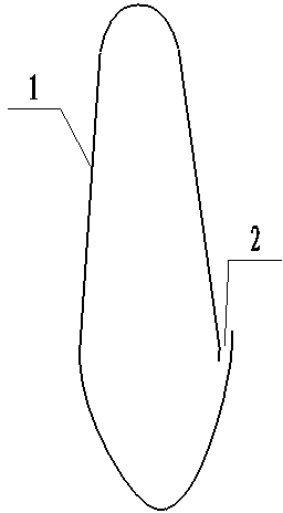
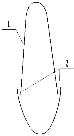
The invention discloses a cooling tower with a draft lifting device, and is applied to the technical field of cooling equipment. The cooling tower with the draft lifting device comprises a cooling tower and an air flow amplifier; the air flow amplifier is installed in the cooling tower and refers to a shell which is of a hollow structure and is made of PVC (polyvinyl chloride) plastics, ABS (acrylonitrile butadiene styrene) plastics or light aluminum materials; fine clearances from which gas can flow out are formed in the side surface of the shell; and the shell is provided with an air inlet. According to the cooling tower, a fluid mechanics principle is utilized, the draft of the cooling tower is improved; the cooling efficiency is improved; the initial construction investment of the cooling tower is saved; and the cooling tower with the draft lifting device is stable and reliable in performance, and is free from maintenance.
Description
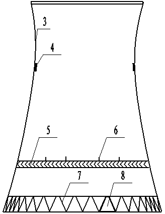
technical field [0001] The invention relates to the technical field of cooling equipment, in particular to a cooling tower with a suction lifting device. Background technique [0002] The waste heat generated in industrial production or refrigeration process should be conducted away with cooling water. The cooling water carrying waste heat exchanges heat with the air in the cooling tower, and through evaporation, the waste heat is transferred to the air and diffused into the atmosphere. In the process of waste heat exchange, the high-temperature cooling water is delivered to the water spreading system on the upper part of the cooling tower through the water pump in the main engine room at a certain pressure, and the hot water is evenly spread on the surface of the filler through the small holes on the water spreader to form water droplets and water films. The dry air enters the cooling tower from the air inlet at the bottom of the cooling tower supported by the herringbon...
Claims
Login to View More Application Information
Patent Timeline
 IPC IPC(8): F28F25/00
Inventor 张书梅徐正余斯北郝中科杜艾洁
Owner POWERCHINA HEBEI ELECTRIC POWER SURVEY & DESIGN INST CO LTD