Eureka AIR delivers breakthrough ideas for toughest innovation challenges, trusted by R&D personnel around the world.

High-vacuum vacuum valve driver

A technology for vacuum valves and drivers, applied to valve details, valve devices, engine components, etc., to achieve fast response

Pending Publication Date: 2020-08-28
SUZHOU AIJIAYA VACUUM TECH CO LTD
View PDF0 Cites 0 Cited by
  • Summary
  • Abstract
  • Description
  • Claims
  • Application Information

AI Technical Summary

Problems solved by technology

However, for die-casting applications, the on-off of the vacuum valve needs to be very sensitive, and the process requirement is within 50ms, which cannot be met with the existing hydraulic system.

Method used


Image

  • High-vacuum vacuum valve driver

Examples


Embodiment

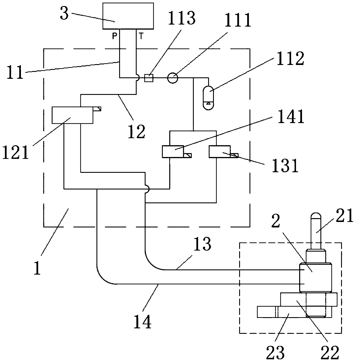
[0019] Such as figure 1 As shown, a high vacuum valve driver of the present invention includes an oil supply pipeline 1 for driving a vacuum valve core 21 capable of telescopic movement in the hydraulic cylinder 2, and the two chambers of the hydraulic cylinder 2 are respectively connected to open the oil circuit 13 and close the oil circuit 14. The oil supply pipeline 1 includes an oil delivery pipe 11 connected to the 3P port of the fuel tank and an oil return pipe 12 connected to the 3T port of the fuel tank. A first electromagnetic valve 131 is provided on the branch connected to the open oil circuit 13, and a second electromagnetic valve 141 is provided on the branch connected to the oil delivery pipe 11 to close the oil circuit 14. The open oil circuit 13 and the closed oil circuit 14 are respectively connected to a The electromagnetic reversing valve 121 on 12, the first electromagnetic valve 131, the second electromagnetic valve 141 and the electromagnetic reversing va...


PUM


Abstract

The invention belongs to the technical field of die casting, and relates to a high-vacuum vacuum valve driver. An oil supply pipeline is included and used for driving a vacuum valve element capable ofdoing the telescopic movement in a hydraulic oil cylinder. Two cavities of the hydraulic oil cylinder are connected with an opening oil path and a closing oil path correspondingly. The oil supply pipeline comprises an oil supply pipe connected with an oil tank port P and an oil return pipe connected with an oil tank port T. The oil supply pipe is sequentially provided with a check valve and an energy accumulator. A branch, connected with the opening oil path, of the oil supply pipe is provided with a first electromagnetic valve. A branch, connected with the closing oil path, of the oil supplypipe is provided with a second electromagnetic valve. Each of the opening oil path and the closing oil path is connected with an electromagnetic reversing valve located on the oil return pipe. The first electromagnetic valve, the second electromagnetic valve and the electromagnetic reversing valve are in linkage control. The two electromagnetic valves are utilized in the mechanism for being matched with the reversing valve for reversing, the response speed of a hydraulically-controlled vacuum valve is higher, the response time can reach 50 ms or below, and die casting air extraction high-precision control is facilitated.

Description

technical field [0001] The invention relates to the technical field of die casting, in particular to a high vacuum valve driver. Background technique [0002] Vacuum metal die-casting technology has been widely used in new energy vehicles, 5G communications, improvement of traditional automotive castings, electronics, household, aviation and other fields. Vacuum die-casting technology is to extract the air in the cavity of the molten metal before cooling and forming. Reduce the injection specific pressure, reduce the porosity, increase the density of the product, and enhance the mechanical properties. Vacuum valve is a very important part in vacuum die casting process. [0003] In order to improve the sensitivity of the vacuum valve, the spool of the vacuum valve is hydraulically controlled, that is, the expansion and contraction of the spool is controlled by alternately filling the front and rear chambers of the hydraulic cylinder. In the past, the hydraulic system only c...

Claims


Application Information

Patent Timeline
Patent Type & Authority Applications(China)
IPC IPC(8): F16K31/12F16K51/02F15B13/044F15B1/02
CPCF15B1/02F15B13/044F16K31/12F16K51/02
Inventor 张军平曹黎明
Owner SUZHOU AIJIAYA VACUUM TECH CO LTD
Why Eureka
Eureka Blog
Learn More