Auxiliary fixing device for railway annunciator

A railway signal machine and fixing device technology, which is applied in the direction of railway signal and safety, supporting machines, mechanical equipment, etc., can solve maintenance problems and achieve the effect of increasing the installation position

Active Publication Date: 2020-08-28
ZHENGZHOU RAILWAY VOCATIONAL & TECH COLLEGE
View PDF13 Cites 2 Cited by
  • Summary
  • Abstract
  • Description
  • Claims
  • Application Information

AI Technical Summary

Problems solved by technology

The auxiliary fixing device of the railway signal machine, by turning the threaded rod, the threaded rod rotates in the threaded sleeve in the center of the side plate, and at the same time moves in the horizontal direction. Connected, the outer wall of the bearing is connected with the inner wall of the bottom cylinder, and the gravity of the bottom cylinder and the pressure plate maintains an effective auxiliary fixation for the railway signal machine, and at the same time simplifies the installation and fixing process of the railway signal machine, and repairs and replaces the railway signal machine It is more convenient and improves the construction efficiency and the practicability of the device; however, this fixing device is too limited for the use environment of the railway signal, and cannot assist the installation of the railway signal in different environments

Method used


Image

  • Auxiliary fixing device for railway annunciator
  • Auxiliary fixing device for railway annunciator
  • Auxiliary fixing device for railway annunciator

Examples


specific Embodiment approach 1

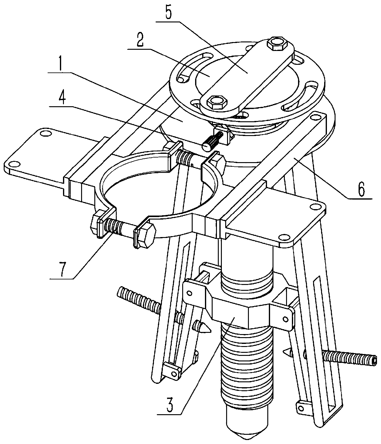
[0031] Such as Figure 1-10 As shown, an auxiliary fixing device for a railway signal machine includes a matching panel 2, a matching tube 201, a matching ring 203, a function port 204, a gear ring II 205, a nail plate 5, a nail rod 501 and a bolt and nut assembly I 502, and the matching panel The lower end of 2 is fixedly connected to and communicated with the matching pipe 201, and the matching ring 203 is fixedly connected to the outer ring end surface of the matching panel 2. The matching ring 203 is uniformly provided with a plurality of functional ports 204 in the circumferential direction, and the gear ring II 205 is fixed on the matching panel. 2, the matching tube 201 is located in the gear ring II 205, the lower end of the nail plate 5 is fixedly connected to the nail bar 501, and the nail bar 501 is slidably connected in the matching tube 201, and the lower end of the nail bar 501 is located below the lower end of the matching tube 201. The plate 5 is attached to th...

specific Embodiment approach 2

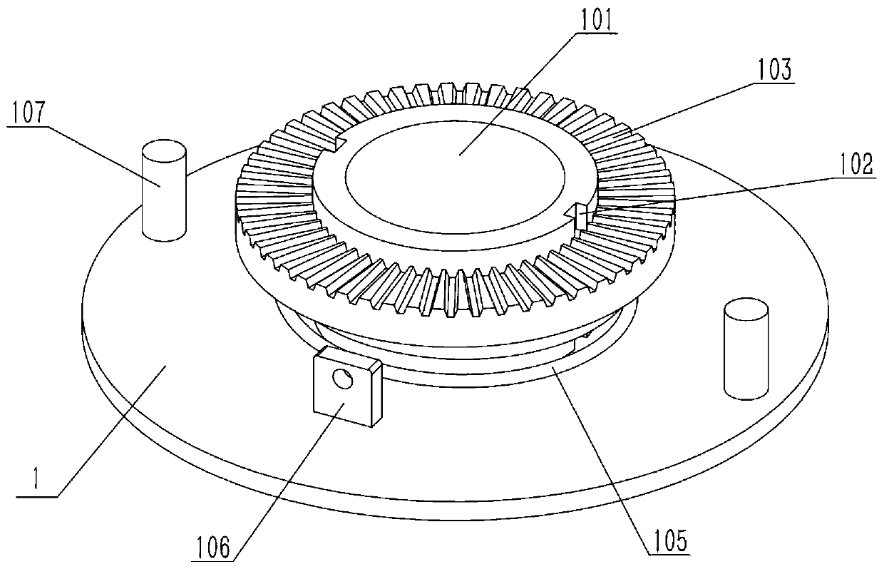
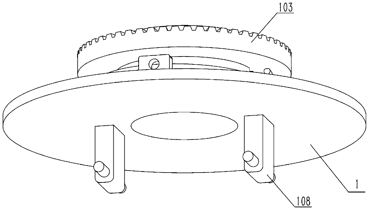
[0033] Such as Figure 1-10 As shown, the railway signal auxiliary fixing device also includes a basic panel 1, a basic pipe 101, a groove 102, a gear ring I 103, a convex part 104, a coil spring 105, a connecting part 108, an external thread 202, a central adjustment platform 3, a connecting Plate 301, connecting seat 302, counter plate 303 and connecting seat II 304, the upper end of the basic panel 1 is fixed and communicated with the basic pipe 101, the outer ring of the basic pipe 101 is provided with a groove 102, and the convex part 104 is fixed on the gear ring I103 , the gear ring I 103 is slidingly connected with the base pipe 101, the convex part 104 is slidingly connected in the groove 102, the coil spring 105 is sleeved on the base tube 101, and the upper and lower ends of the coil spring 105 are respectively in contact with the gear ring I 103 and the base panel 1, The left and right sides of the lower end of the basic panel 1 are fixedly connected with a connect...

specific Embodiment approach 3

[0035] Such as Figure 1-10 As shown, the auxiliary fixing device of the railway signal machine also includes a screw plate 106, a rod head 4, a screw II 401 and a pad 402. The screw plate 106 is fixed on the foundation panel 1, and the front end of the rod head 4 is fixed to the screw rod II 401. , the front end of the screw rod II 401 is fixedly connected to the cushion block 402 , the screw rod II 401 is threadedly connected to the screw plate 106 , and the cushion block 402 is located on the lower side of the gear ring I 103 . Rotate the rod head 4, the rod head 4 drives the screw rod II 401 to rotate, the screw rod II 401 drives the block 402 to rotate, make the block 402 vertical, and then use the block 402 to push the gear ring I103 up to keep the gear ring I103 and the gear ring II205 engaged, and then make the The matching tube 201 will not rotate when subjected to external force, and remains in a clamped state.


PUM


Abstract

The invention relates to an annunciator fixing device, in particular to an auxiliary fixing device for a railway annunciator. The device comprises a matching panel, a matching pipe, a matching ring, function openings, a gear ring II, a nail plate, a nail rod and bolt and nut assemblies I. The railway annunciator can be installed on a soil base beside a rail through the nail rod. The railway annunciator can be inserted through two abutting plates into a gap, such as a gap existing in a mountain slope, a gap between rocks or a self-built groove. The railway annunciator can sleeve a cylinder by utilizing two adjustable arc parts. The two abutting plates are unfolded to be in a horizontal state, and the rail annunciator can be installed on a wall body with a flat wall face. A mounting plate Iand a mounting plate II can be used for increasing the mounting position of the rail annunciator, and multi-path signal providing is facilitated.

Description

technical field [0001] The invention relates to a signal fixing device, in particular to an auxiliary fixing device for a railway signal. Background technique [0002] For example, the publication number is CN208365082U, an auxiliary fixing device for a railway signal machine, which includes a railway signal machine, a pillar is installed at the lower end of the railway signal machine, the lower end of the pillar is connected with the surface of the first base plate, and the support plate passes through the support plate. In the center, the left central outer wall of the pillar is overlapped with the right surface of the first baffle, and the left surface of the first baffle is connected with the support plate. The auxiliary fixing device of the railway signal machine, by turning the threaded rod, the threaded rod rotates in the threaded sleeve in the center of the side plate, and at the same time moves in the horizontal direction. Connected, the outer wall of the bearing i...

Claims


Application Information

Patent Timeline
Patent Type & Authority Applications(China)
IPC IPC(8): F16M13/02F16M7/00B61L5/00
CPCB61L5/00F16M7/00F16M13/02
Inventor 王秀玄魏君占雪梅马芳李珊珊孟斌吕兴瑞
Owner ZHENGZHOU RAILWAY VOCATIONAL & TECH COLLEGE
Why Eureka
Try Eureka