Coaxial double-rotor helicopter transmission device with bevel gear branching

A technology of coaxial double-rotors and transmissions, which is applied to gear transmissions, transmissions, transmission parts, etc., can solve the problems of large transmissions, high manufacturing precision requirements, and reduced installation efficiency, so as to improve stability and Reliability, volume and weight reduction, and the effect of reducing the load of each branch

Inactive Publication Date: 2020-09-25
NANJING UNIV OF AERONAUTICS & ASTRONAUTICS
View PDF6 Cites 2 Cited by
  • Summary
  • Abstract
  • Description
  • Claims
  • Application Information

AI Technical Summary

Problems solved by technology

However, due to the structural strength and efficiency of the planetary gear transmission, its transmission is relatively small; at the same time, the planetary gear has both revolution and rotation, so the structure is complicated, and the working conditions of the supporting bearing are complicated, the bearing is easily damaged, and the seal is poor. The moving planetary gear train is difficult to match the teeth, the structure is more complex, the manufacturing precision is high, and the manufacturing and installation are more difficult
[0004] In this regard, the State Intellectual Property Office announced on May 3, 2019 a Chinese invention patent titled "Coaxial double-rotor transmission with two power splits between bevel gear and cylindrical gear" with the application number "201910011019.9" , in this case, two bevel gears with the same axis are meshed by one input bevel gear at the same time, so as to realize two-way transmission and power splitting; A large space is left in the axial direction of the two power output shafts to facilitate the arrangement of the input bevel gears; thus, the transmission device is large in size and complex in design and layou

Method used


Image

  • Coaxial double-rotor helicopter transmission device with bevel gear branching
  • Coaxial double-rotor helicopter transmission device with bevel gear branching
  • Coaxial double-rotor helicopter transmission device with bevel gear branching

Examples


Embodiment Construction

[0044] In order to clearly illustrate the technical characteristics of this patent, the following describes this patent in detail through specific implementation methods and in conjunction with the accompanying drawings.

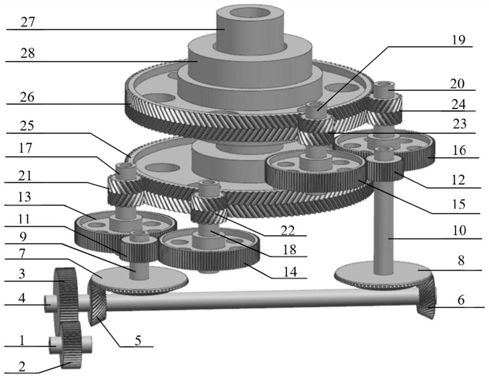
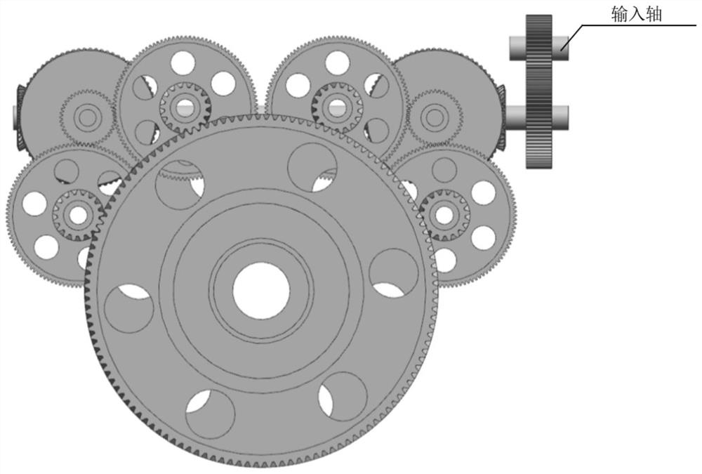
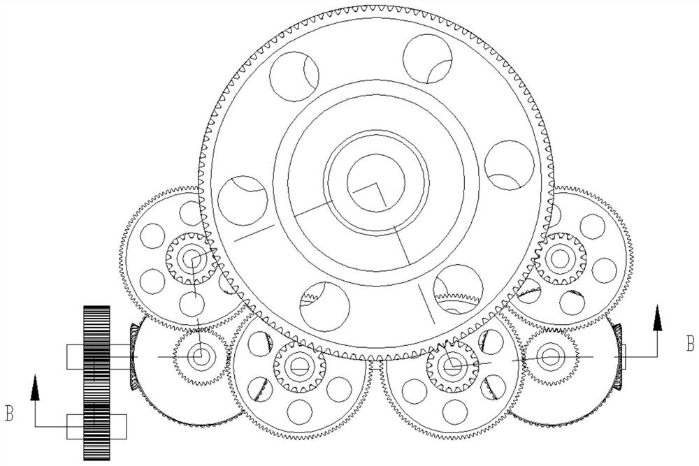
[0045] The present invention as Figure 1-8 As shown, comprising an output unit and at least one power input shunt unit;

[0046] The output unit includes a coaxial inner rotor shaft 27 and an outer rotor shaft 28; the inner rotor shaft 27 is connected to the upper rotor, the outer rotor shaft 28 is connected to the lower rotor, and the outer rotor shaft 28 is sleeved on the The outside of the inner rotor shaft 27, and the two keep the coaxial center, thereby forming a coaxial double rotor structure;

[0047] The power input split unit includes an input shaft 1, a first gear shaft 4, a second gear shaft 9, a third gear shaft 10, a fourth gear shaft 17, a fifth gear shaft 18, a sixth gear shaft 19 and a seventh gear Shaft 20; the input shaft 1 is linked wit...


PUM


Abstract

The invention discloses a coaxial double-rotor helicopter transmission device with bevel gear branching, and relates to the field of coaxial double-rotor helicopter transmission system configuration.The coaxial double-rotor helicopter transmission device with the bevel gear branching has very important significance for a high-power high-speed transmission system. According to the technical scheme, the coaxial double-rotor helicopter transmission device with the bevel gear branching comprises an output unit and at least one power input shunting unit, wherein the output unit comprises an innerrotor shaft 27 and an outer rotor shaft 28; and the power input shunting unit comprises an input shaft 1, a first gear shaft 4, a second gear shaft 9, a third gear shaft 10, a fourth gear shaft 17 anda sixth gear shaft 19. The transmission system configuration can be widely applied to the fields of medium and heavy helicopter transmission systems, ship transmission systems and the like. The sizeand weight of the whole transmission system can be effectively reduced, and the stability and reliability of the system are improved.

Description

technical field [0001] The present invention relates to the configuration field of coaxial double-rotor helicopter transmission system, in particular to a coaxial double-rotor helicopter transmission device with bevel gear branching, which is a kind of transmission device which utilizes bevel gear branching to complete commutation and deceleration to realize coaxial Reversed coaxial twin-rotor helicopter main reducer transmission configuration. Background technique [0002] The helicopter transmission system, together with the engine and the rotor system, are called the three key moving parts of the helicopter. Its function is to transmit the output power and output speed of the engine to the rotor, tail rotor and various accessories in a certain proportion. The transmission system of the coaxial twin-rotor helicopter is more complicated than that of the single-rotor helicopter, because one engine of the coaxial twin-rotor helicopter must simultaneously drive the upper and l...

Claims


Application Information

Patent Timeline
IPC IPC(8): F16H1/22F16H57/023B64C27/12
CPCB64C27/12F16H1/222F16H57/023F16H2057/02039F16H2057/02086F16H2057/02091
Inventor 张玉姣朱如鹏李苗苗张栋林倪德王永红
Owner NANJING UNIV OF AERONAUTICS & ASTRONAUTICS
Why Eureka
Try Eureka