Wheel steering system

a technology of steering system and wheel, which is applied in the direction of steering linkage, electrical steering, transportation and packaging, etc., can solve the problems of degrading travel performance, increasing the size of actuators, so as to reduce manufacturing costs, reduce weight, and simplify the structure

Active Publication Date: 2020-10-13
HONDA MOTOR CO LTD
View PDF30 Cites 0 Cited by
  • Summary
  • Abstract
  • Description
  • Claims
  • Application Information

AI Technical Summary

Benefits of technology

[0010]The present invention provides a wheel steering system that has a simple structure to have less weight, to have less manufacturing costs, and to allow for increasing a cabin space.

Problems solved by technology

Incidentally, an actuator in the prior art is complicated in structure to include many parts, so that it has likely been increased in size.
In addition, if the toe angle of the wheel is to be varied more widely, the actuator may be further increased in size to have an increased weight and this causes traveling performance to be degraded.
Further, this increases manufacturing costs and causes an arm or arms for supporting the actuator also to be increased in size, so that a cabin space is reduced.
As described above, the actuators and the arms are increased in size in the case where the wheel steering system is to be steered with an increased steering angle, to make it difficult for those components being layed out in a conventional cabin space.
As a result, a space for laying out such a suspension system needs to be secured at the expense of the cabin space.

Method used


Image

  • Wheel steering system
  • Wheel steering system
  • Wheel steering system

Examples


Embodiment Construction

[0021]Hereinafter, embodiments of the present invention will be described in detail with reference to the drawings as appropriate.

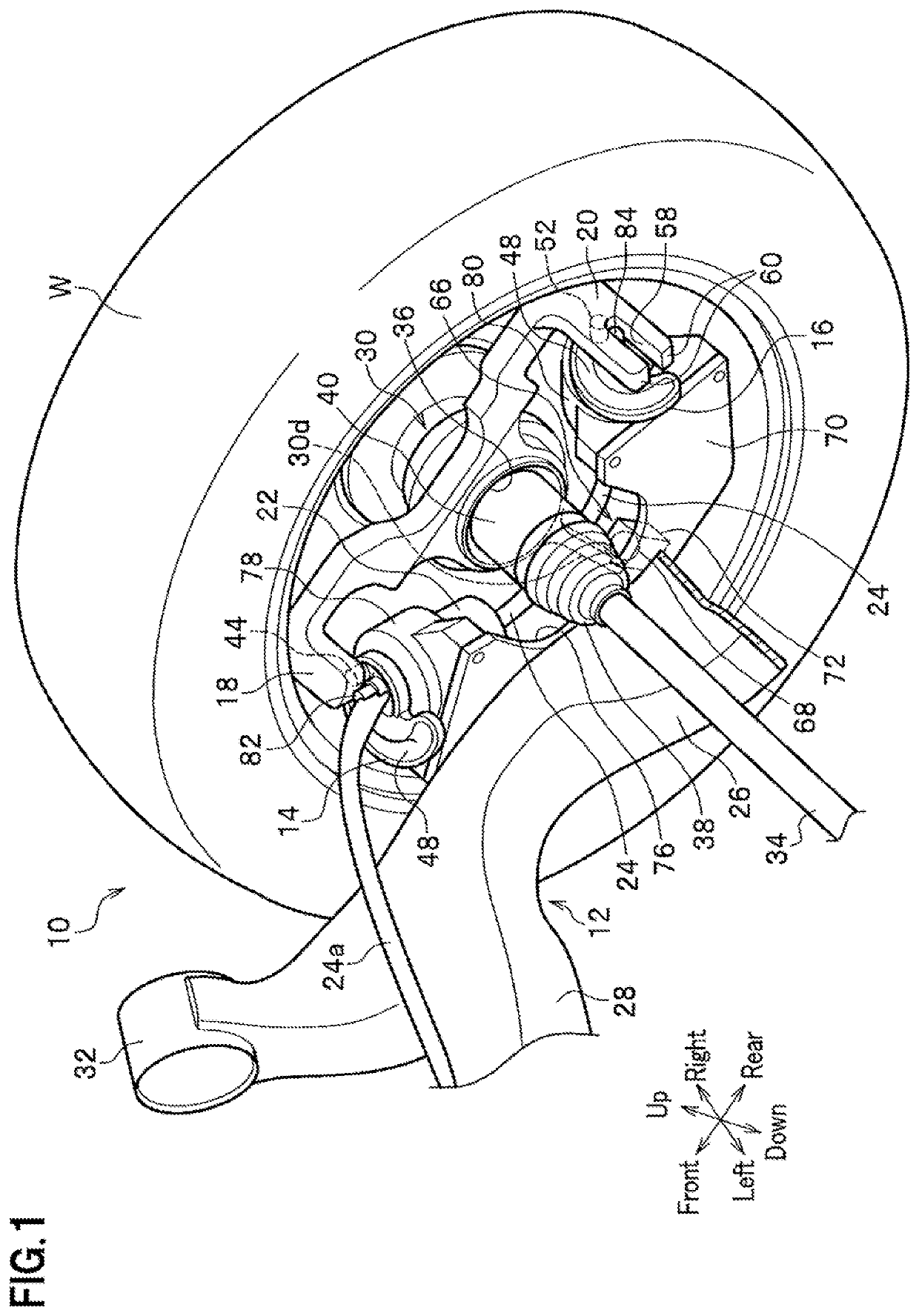
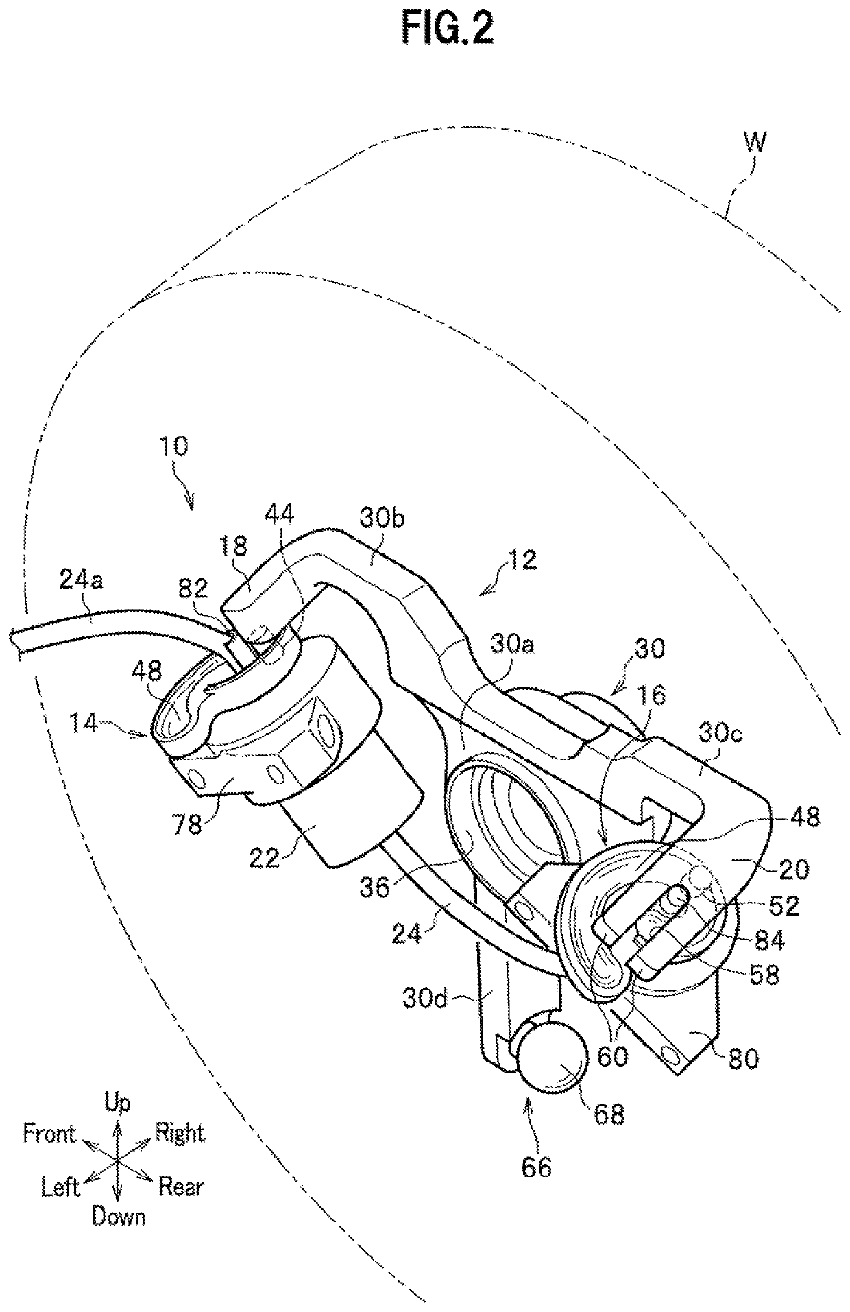
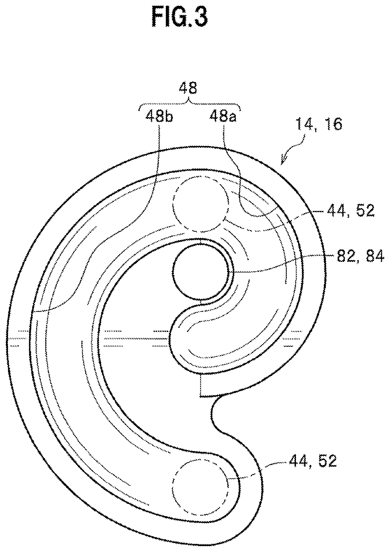
[0022]FIG. 1 is a perspective view of a right rear wheel of a vehicle, partially sheared, having a rear suspension device according to an embodiment of the present invention, FIG. 2 is a perspective view of the rear suspension device in FIG. 1, partially unshown, and FIG. 3 is an enlarged plan view of a first cam (or second cam). Note that in each figure, an arrowed line “front-rear” indicates a vehicle front-rear direction, an arrowed line “right-left” indicates a vehicle width direction (right-left direction), and an arrowed line “up-down” indicates a vehicle up-down direction (vertical vertical direction).

[0023]A rear suspension device 10 according to the embodiment of the present invention is applied to a vehicle (not shown) employing a four-wheel drive system, as an example. As shown in FIGS. 1 and 2, the rear suspension device 10 includes a rear sus...


PUM


Abstract

A wheel steering system includes: a rear suspension mechanism inclusive of a knuckle member for rotatably holding a right rear wheel; a first cam and a second cam that are rotatably supported; a first cam follower 18 that follows the first cam; a second cam follower 20 that follows the second cam 16; cam grooves 48 respectively provided in the first and second cams; a first engaging pin and a second engaging pin that engage with the respective cam grooves; and a rotational driving force transmitter that transmits a rotational driving force of an electric motor to the first and second cams, wherein the first cam and the first cam follower are arranged on a front side in the vehicle front-rear direction of an axle, and the second cam and the second cam follower are arranged on a rear side in the vehicle front-rear direction of the axle.

Description

CROSS-REFERENCE TO RELATED APPLICATION[0001]This application claims the benefit of priority to Japanese Patent Application No. 2017-226663 filed 27 Nov. 2017, the disclosures of all of which are hereby incorporated by reference in their entireties.TECHNICAL FIELD[0002]The present invention relates to a wheel steering system for a vehicle.BACKGROUND OF THE INVENTION[0003]Japanese Patent No. 4868129 B2 (hereinbelow, referred to as Patent Document 1), as an example, discloses a wheel steering system that uses two actuators, which are arranged along a vehicle traveling direction, to change a toe angle (steering angle) of a wheel.[0004]In addition, Japanese Patent No. 4867460 B2 discloses a wheel steering system that uses an actuator including three hydraulic cylinders, which are equiangularly arranged along the circumferential direction, to change a toe angle (steering angle) of a wheel.SUMMARY OF THE INVENTIONProblems to be Solved[0005]Incidentally, an actuator in the prior art is comp...

Claims


Application Information

Patent Timeline
Patent Type & Authority Patents(United States)
IPC IPC(8): B62D7/18B62D7/16B62D7/20B60G21/05B62D17/00
CPCB62D7/18B60G21/051B62D17/00B62D7/20B60G2500/40B62D7/166B60G2204/42B60G2204/62B60G2200/422B60G2206/20B60G2200/44B60G2200/462B60G2206/50B60G2202/442B60G2202/42B62D3/02B62D5/04
Inventor YAMAZAKI, RYOSUKEINAGAKI, TAKUMI
Owner HONDA MOTOR CO LTD
Why Eureka
Try Eureka