Drying main unit of continuous grain drying device

A kind of drying equipment and continuous technology, which is applied in the direction of dryers, dryers for static materials, drying, etc., can solve problems such as troubles, achieve convenient control, convenient drying time, and realize the effects of dumping and returning

Inactive Publication Date: 2020-08-28
TAIZHOU LEYAN AUTOMATION SCIEN-TECH CO LTD
View PDF8 Cites 1 Cited by
  • Summary
  • Abstract
  • Description
  • Claims
  • Application Information

AI Technical Summary

Problems solved by technology

[0002] The existing grains and nuts need to be dried after harvesting, and in the existing drying equipment, a drying mechanism such as a heating rod is generally set on one part above the conveying frame, and the material is dried when passing through the heating rod. Dry, and then transported out, its efficiency is high, but because the drying time under the heating rod is controlled according to the conveying speed of the conveyor belt, the control of the drying time requires the conveying adjustment of the entire conveying mechanism, which is very trouble

Method used


Image

  • Drying main unit of continuous grain drying device
  • Drying main unit of continuous grain drying device
  • Drying main unit of continuous grain drying device

Examples


Embodiment Construction

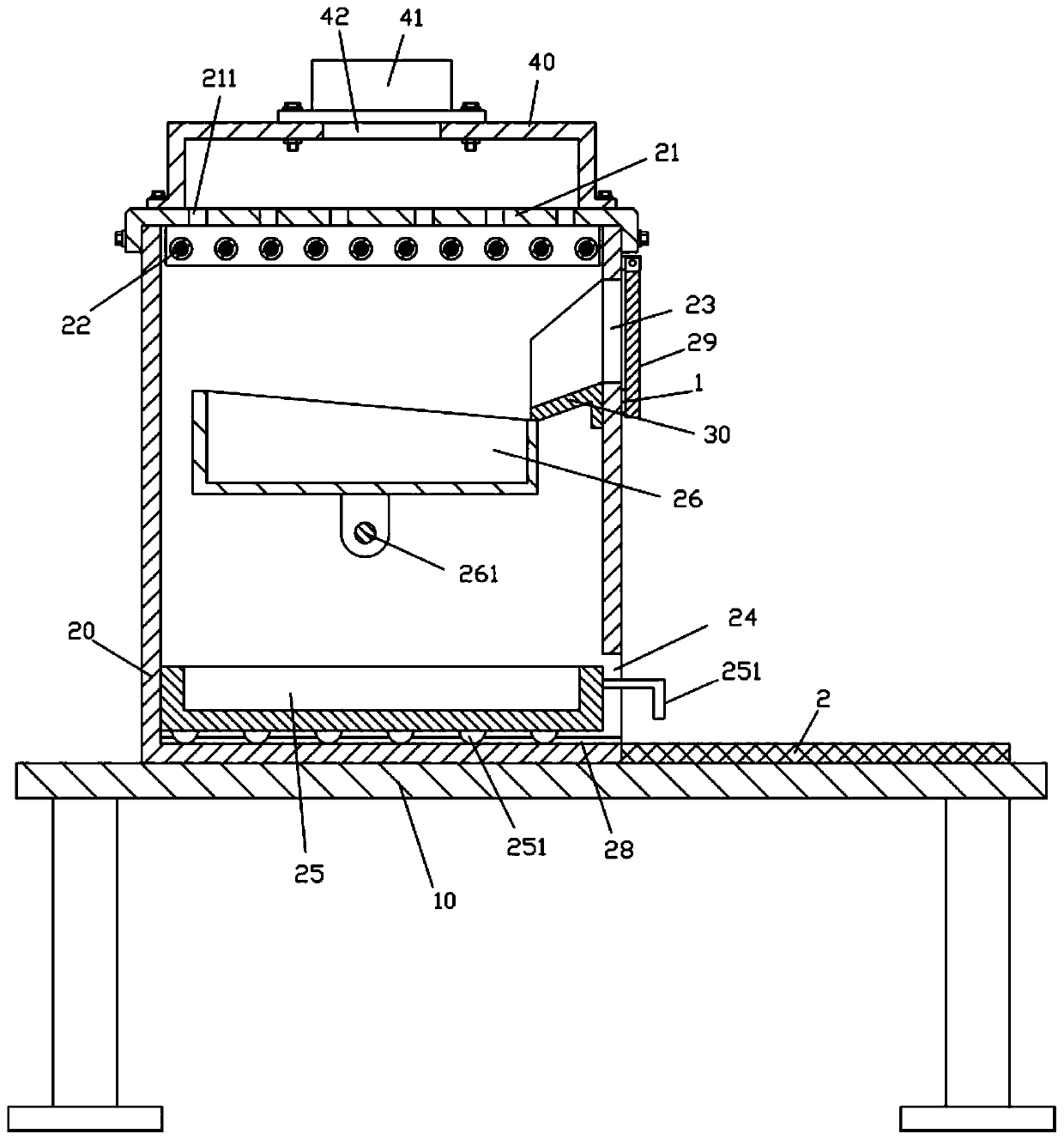
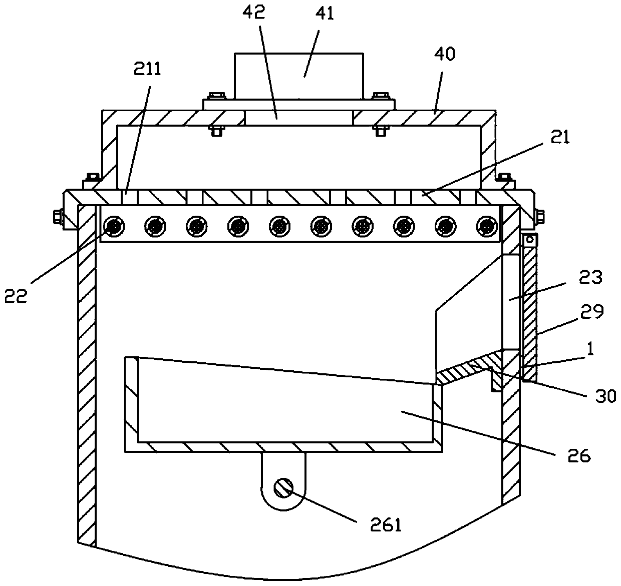
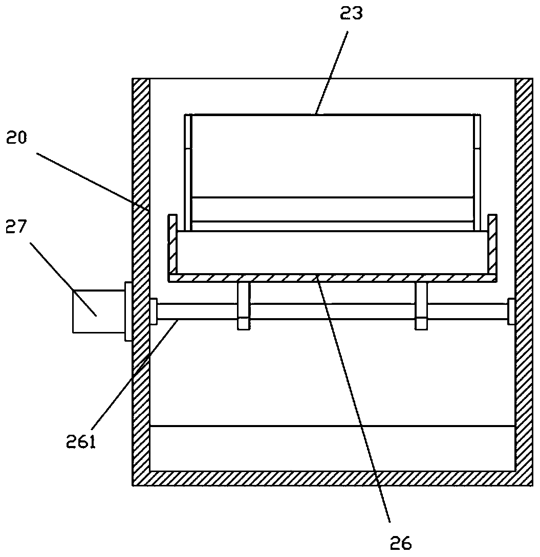
[0018] Examples, see e.g. Figure 1 to Figure 3 As shown, a drying host of a grain continuous drying equipment includes a main frame 10, a main box body 20 is fixed on the top surface of the top plate of the main frame 10, and an upper top plate 21 is fixed on the top of the main box body 20, A plurality of heating rods 22 are fixed on the bottom surface of the upper top plate 21;

[0019] The upper part of the right side plate of the main box body 20 is formed with a feeding channel 23, the lower part of the right side plate of the main box body 20 is formed with a discharge channel 24, and the material receiving channel body 25 is located on the bottom plate of the main box body 20. On the top surface of the top surface, a handle 251 is fixed on the right side wall of the material receiving tank body 25, and the handle 251 is inserted and sleeved in the discharge channel 24;

[0020] The upper part of the main box body 20 is provided with a middle drying tank 26, the middle...


PUM


Abstract

The invention discloses a drying main unit of a continuous grain drying device. The drying main unit comprises a main unit frame, a main box is fixed to the top surface of a top plate of the main unitframe, an upper top plate is fixed to the top of the main box, and a plurality of heating rods are fixed to the bottom surface of the upper top plate; and a feeding through groove is formed in the upper portion of a right side plate of the main box, a discharging through groove is formed in the lower portion of the right side plate of the main box, a receiving tank is located on the top surface of a bottom plate of the main box, a handle is fixed to the right side wall of the receiving tank, and the handle is inserted in the discharging through groove in a sleeved manner. According to the drying main unit, materials such as grains or nuts can be poured into a middle drying tank to be dried, after drying is completed, the middle drying tank can turn over and pour the materials into the receiving tank through operation of a driving servo motor, discharging can be achieved by pulling out the receiving tank, and the process is very convenient; and as the middle drying tank is independently controlled by the driving servo motor, the drying time of the middle drying tank is convenient to control, and pouring and returning can be achieved just by controlling the operation and stop of thedriving servo motor.

Description

technical field [0001] The invention relates to the technical field of agricultural machinery and equipment, in particular to a drying host of continuous grain drying equipment. Background technique [0002] The existing grains and nuts need to be dried after harvesting, and in the existing drying equipment, a drying mechanism such as a heating rod is generally set on one part above the conveying frame, and the material is dried when passing through the heating rod. Dry, and then transported out, its efficiency is high, but because the drying time under the heating rod is controlled according to the conveying speed of the conveyor belt, the control of the drying time requires the conveying adjustment of the entire conveying mechanism, which is very trouble. Contents of the invention [0003] The purpose of the present invention is to overcome the deficiencies of the prior art and provide a drying host of continuous grain drying equipment, which can pour materials such as ...

Claims


Application Information

Patent Timeline
Patent Type & Authority Applications(China)
IPC IPC(8): F26B9/06F26B21/00F26B23/00F26B25/18F26B25/10
CPCF26B9/06F26B21/001F26B23/00F26B25/10F26B25/18
Inventor 胡帮
Owner TAIZHOU LEYAN AUTOMATION SCIEN-TECH CO LTD
Why Eureka
Try Eureka