Circuit topology and energy management strategy of a micro smart power station

A topology and energy management technology, applied in battery circuit devices, circuit devices, AC network circuits, etc., can solve problems such as increased power loss, increased manufacturing costs, stability of distributed port smart transformers, and economic threats. Improve power density and operating efficiency, save power conversion links, and facilitate modular expansion

Active Publication Date: 2021-09-03
NANJING UNIV OF SCI & TECH
View PDF7 Cites 0 Cited by
  • Summary
  • Abstract
  • Description
  • Claims
  • Application Information

AI Technical Summary

Problems solved by technology

Sudden changes in port power and poor local power mobility will pose a great threat to the stability and economy of distributed port smart transformers, which is unacceptable for distributed energy smart transformers
Usually, the distributed low-voltage ports are realized through the parallel connection of the DC output terminals of each power unit. If you want to connect distributed energy sources, you will inevitably be limited by the voltage level, which leads to the need to add subsequent power conversion links, thereby increasing power loss and causing Reduced power transmission efficiency and increased manufacturing costs have a greater impact on the economics of distributed energy interconnection / grid-connection

Method used


Image

  • Circuit topology and energy management strategy of a micro smart power station
  • Circuit topology and energy management strategy of a micro smart power station
  • Circuit topology and energy management strategy of a micro smart power station

Examples


Embodiment 1

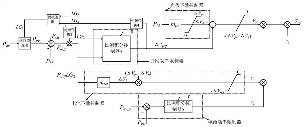
[0062] The load power decreases or increases, resulting in the redistribution of the power of each port of the hybrid power unit; when the maximum power generated by the solar photovoltaic panel P pv_m For its rated value, take a hybrid power unit as an example to illustrate the impact of load power reduction or increase on its power distribution at each port.

[0063] Such as Figure 7 As shown, when the load power P ld is 0, the operating point of the hybrid power unit on the DC power-voltage curve is at A 1 point, the operating point of the AC power-voltage curve is located at A 2 point, the active power output to the high-voltage AC grid is P ac1 , the charging power of the battery is P ch , the photovoltaic power generation is Ppv-1 , the relationship between port power satisfies: P pv-1 =P ch +P ac1 ;

[0064] When the load power increases to P ld-2 , the operating point of the hybrid power unit on the DC power-voltage curve starts from A 1 The point moves alo...

Embodiment 2

[0071] The decrease or increase of the load power leads to the redistribution of the power of each port of the hybrid power unit; affected by the actual operating environment, the maximum power of photovoltaic power generation may be less than the rated value. For this situation, a hybrid power unit is used as an example below Describe the impact of load power reduction or increase on the power distribution of each port.

[0072] Such as Figure 8 As shown, when the load power is 0, the operating point of the hybrid power unit on the DC power-voltage curve is at A 1 point, the operating point of the AC power-voltage curve is located at A 2 point, the active power output to the high-voltage AC grid is P ac1 , the charging power of the battery is P ch , the photovoltaic power generation power is P pv-1 , the relationship between port power satisfies: P pv-1 =P ch +P ac1 ;

[0073] When the load power increases to P ld-2 , the operating point of the hybrid power unit on ...


PUM


Abstract

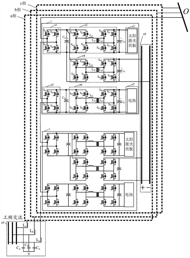
The invention discloses a circuit topology structure of a miniature intelligent power station and an energy management strategy thereof. The circuit topology of the micro smart power station includes three phases a, b and c with the same structure, and each phase includes N hybrid power units and a DC bus a8; N hybrid power units are connected in sequence, and each phase of the hybrid power One AC output terminal of the unit is connected to a point O, the DC output terminal of each hybrid power unit is connected to the DC bus a8, one AC output terminal of the nth hybrid power unit of each phase is connected to the other of the n-1th hybrid power unit One AC output terminal is connected, and the AC voltage output terminal of each phase hybrid power unit is connected with the high-voltage AC grid a9. The energy management strategy of the present invention realizes smooth switching of grid-connected / off-grid operation modes according to loads and real-time demands of the power grid.

Description

technical field [0001] The invention belongs to the field of distributed integrated power supply control, and specifically relates to a circuit topology structure of a miniature intelligent power station and an energy management strategy thereof. Background technique [0002] A distributed integrated energy system is an energy system that effectively and reliably connects power generation, energy storage, and power consumption through a specific topology network and terminal power equipment. With the introduction of the concept of global energy Internet, distributed integrated energy systems of various types, forms, and scales are developing rapidly. However, the power routing performance of distributed port smart transformers largely depends on the degree of port power decoupling and power path flexibility. Sudden changes in port power and poor local power mobility will pose a great threat to the stability and economy of distributed port smart transformers, which is unacce...

Claims


Application Information

Patent Timeline
Patent Type & Authority Patents(China)
IPC IPC(8): H02J3/38H02J3/32H02J3/46H02J3/48H02J7/35H02J1/10H02J4/00
CPCH02J1/10H02J3/32H02J3/381H02J3/48H02J4/00H02J7/35H02J3/466H02J2300/24H02J2300/26Y02E10/56
Inventor 汪诚彭合李磊
Owner NANJING UNIV OF SCI & TECH
Why Eureka
Try Eureka