Electromagnetic brake motor

A technology of electromagnetic braking and electric motor, applied in the direction of electric components, control mechanical energy, electrical components, etc., can solve the problems of friction lining resistance, the size of the friction lining should not be too small, energy waste, etc., to achieve the effect of efficient heat dissipation

Active Publication Date: 2020-08-28
浙江奇志电机股份有限公司
View PDF10 Cites 3 Cited by
  • Summary
  • Abstract
  • Description
  • Claims
  • Application Information

AI Technical Summary

Problems solved by technology

[0004] The above-mentioned existing technical solutions have the following defects: in order to achieve a better braking effect, the friction plate needs a certain braking contact area, so the size of the friction plate should not be too small; the rotating shaft of the motor continues to drive the friction plate Rotation, the friction plate will cause resistance to the rotation of the shaft during operation, especially when the motor starts or the speed increases, there is a waste of energy

Method used


Image

  • Electromagnetic brake motor
  • Electromagnetic brake motor
  • Electromagnetic brake motor

Examples


Embodiment Construction

[0035] The present invention will be described in further detail below in conjunction with the accompanying drawings.

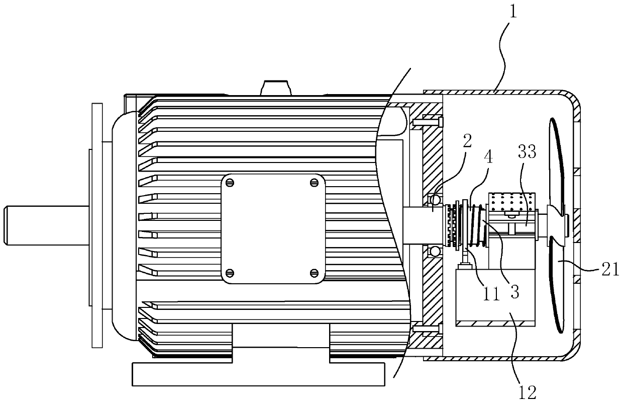
[0036] refer to figure 1 and figure 2 , is an electromagnetic braking motor disclosed in the present invention, comprising a casing 1 and a rotating shaft 2, the rotating shaft 2 is fixed with a rotor and an output shaft for output torque, an electromagnet 11 is fixed inside the casing 1, and the rotating shaft 2 is covered A brake shaft 3 is provided, a fan 21 is fixedly connected to the end of the rotating shaft 2 , and a door-shaped base 12 is fixed inside the casing 1 .

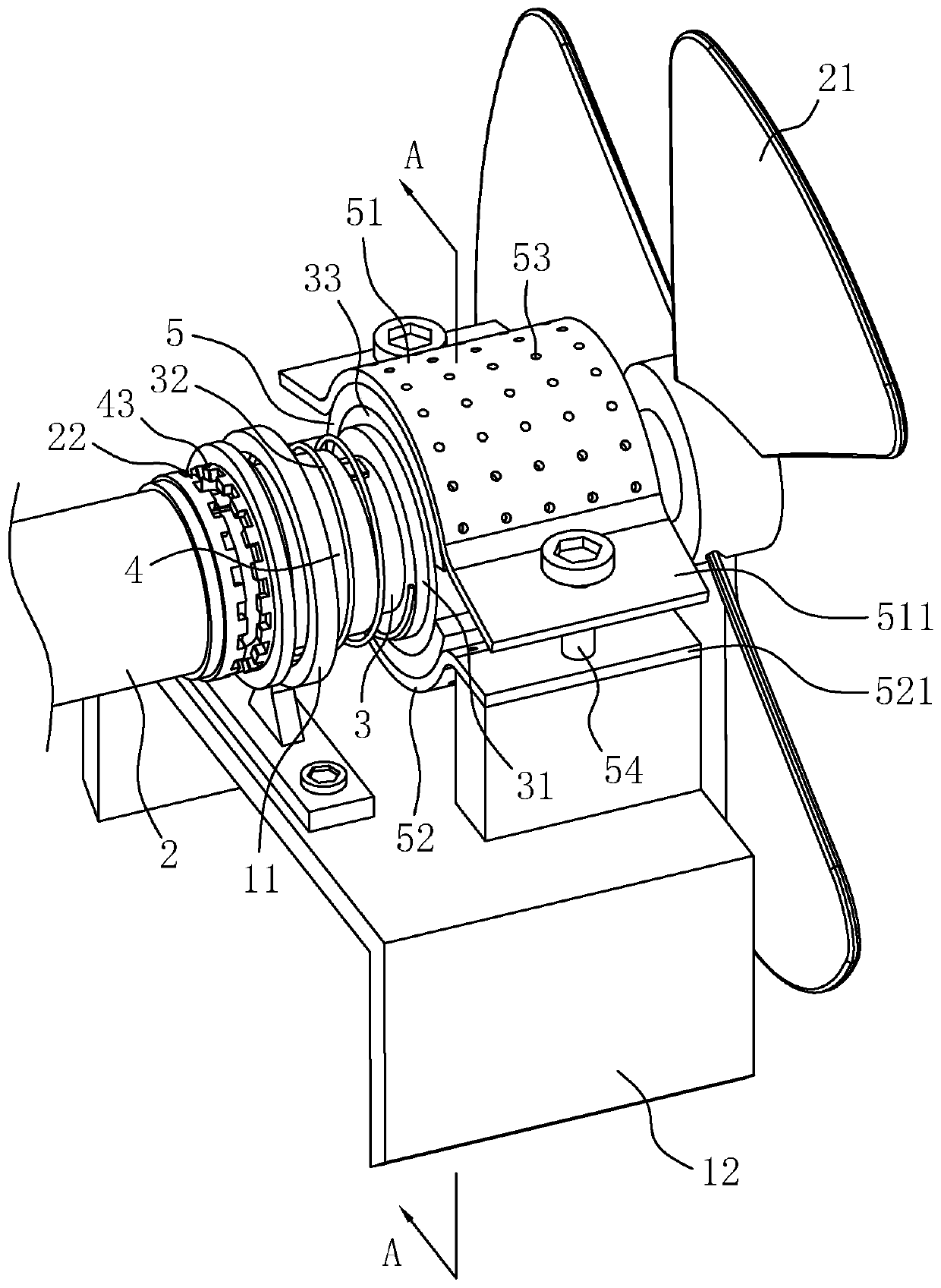
[0037] refer to figure 2 and image 3 , the axis of the braking shaft 3 coincides with the axis of the rotating shaft 2. The braking shaft 3 is made of copper as a whole. The inner hole wall is in rotational contact, and the brake shaft 3 made of copper has less friction with the rotating shaft 2, which can be used for a long time.

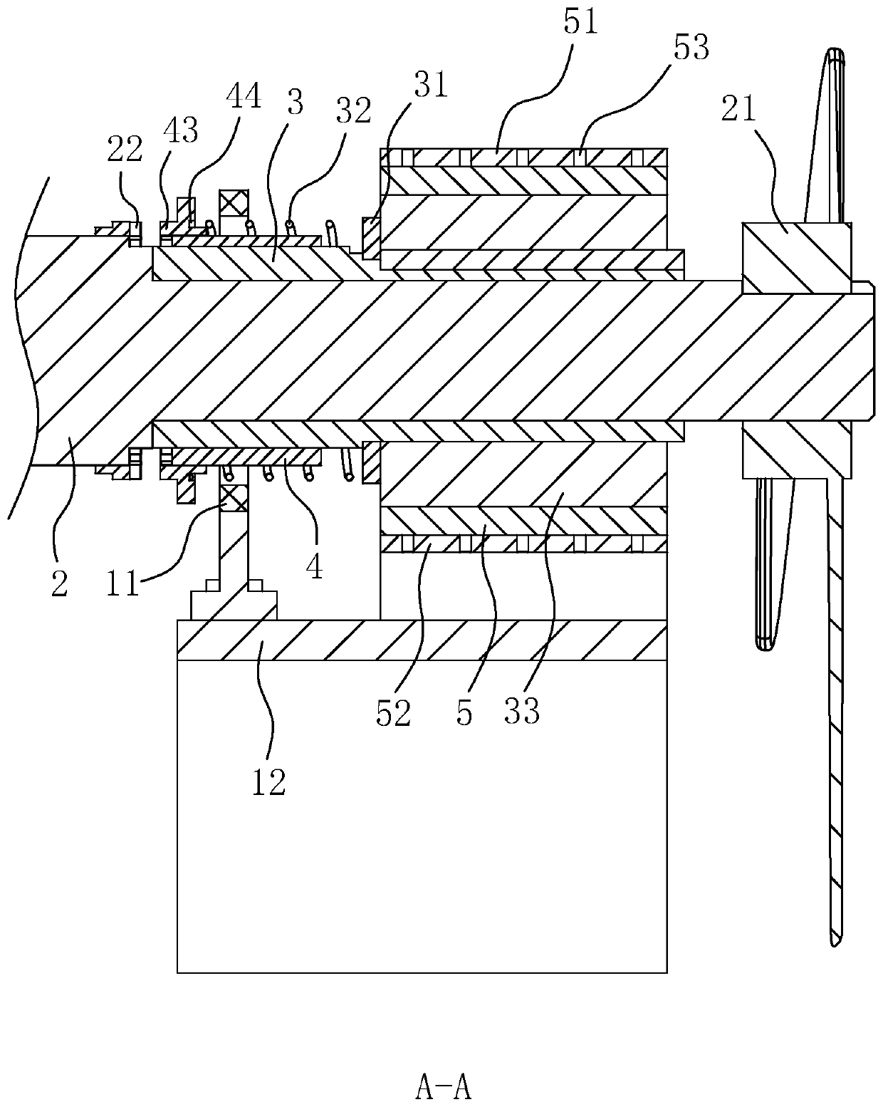
[0038] refer to image 3 and Figure 4 , the ...


PUM


Abstract

The invention discloses an electromagnetic brake motor, and relates to the technical field of motors. According to the technical scheme, the electromagnetic brake motor comprises a machine shell, a rotating shaft and an electromagnet, wherein a brake shaft is rotationally arranged in the machine shell, the brake shaft is sleeved with a clutch cylinder, the clutch cylinder can slide in the axial direction of the brake shaft but cannot continuously rotate around the brake shaft, the rotating shaft is provided with a first tooth part facing the clutch cylinder, the end, facing the first tooth part, of the clutch cylinder is provided with a second tooth part, a spring is arranged between the clutch cylinder and the brake shaft, the elastic force of a spring drives the first tooth part and thesecond tooth part to be connected in an inserted mode, the clutch cylinder is made of a ferromagnetic material, the electromagnet right faces the clutch cylinder, a friction disc is fixed to the brakeshaft, a brake disc is fixed to the machine shell, and the friction disc and the brake disc are kept in an abutting state. When the motor operates normally, the brake shaft and the friction disc do not rotate, so that an energy-saving effect is achieved; when the power supply of the motor is cut off accidentally, the motor can still realize automatic braking of the rotating shaft, so that the motor is relatively safe; and heat dissipation of the friction disc and the brake disc is efficient.

Description

technical field [0001] The invention relates to the technical field of motors, in particular to an electromagnetic braking motor. Background technique [0002] Motor refers to the power device that converts electrical energy into mechanical energy (rotation form) according to the law of electromagnetic induction, and is widely used in various mechanical equipment. After the motor is powered off, the shaft, rotor and the objects it drives will continue to rotate for a period of time due to inertia. Due to factors such as safety or processing efficiency, in many cases, the motor needs to stop rotating quickly after power off. At present, in order to realize the rapid stop of the motor, the electromagnetic brake is often used in technology to quickly stop the rotating shaft. [0003] The Chinese invention patent application with the existing application publication number CN106787424A discloses an electromagnetic brake motor, which includes a motor body, an end cover with vent...

Claims


Application Information

Patent Timeline
Patent Type & Authority Applications(China)
IPC IPC(8): H02K7/112
CPCH02K7/1125
Inventor 卢禹诚
Owner 浙江奇志电机股份有限公司
Why Eureka
Try Eureka