Glass drying equipment and glass drying method for touch screen processing

A technology of drying equipment and touch screen, which is applied in glass manufacturing equipment, glass transportation equipment, lighting and heating equipment, etc. It can solve the problems of easy scratched glass, easy scratched silk screen pattern, glass easy to slip, etc. It is not easy to achieve Slipping, safe handling, and high safety effects

Active Publication Date: 2021-05-25
GANZHOU LIDE ELECTRONICS CO LTD
View PDF8 Cites 0 Cited by
  • Summary
  • Abstract
  • Description
  • Claims
  • Application Information

AI Technical Summary

Problems solved by technology

[0005] The screen-printed glass is easy to slip and cause damage to the glass;
[0006] It is easy to scratch the silk screen pattern when using gloves to carry the glass;
[0007] The glass slides in the slot and is easy to scratch the glass

Method used


Image

  • Glass drying equipment and glass drying method for touch screen processing
  • Glass drying equipment and glass drying method for touch screen processing
  • Glass drying equipment and glass drying method for touch screen processing

Examples


Embodiment 1

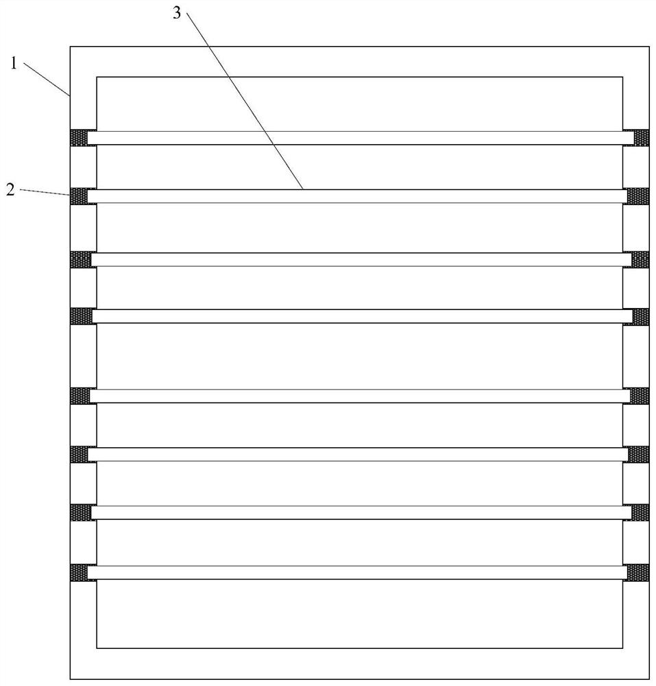
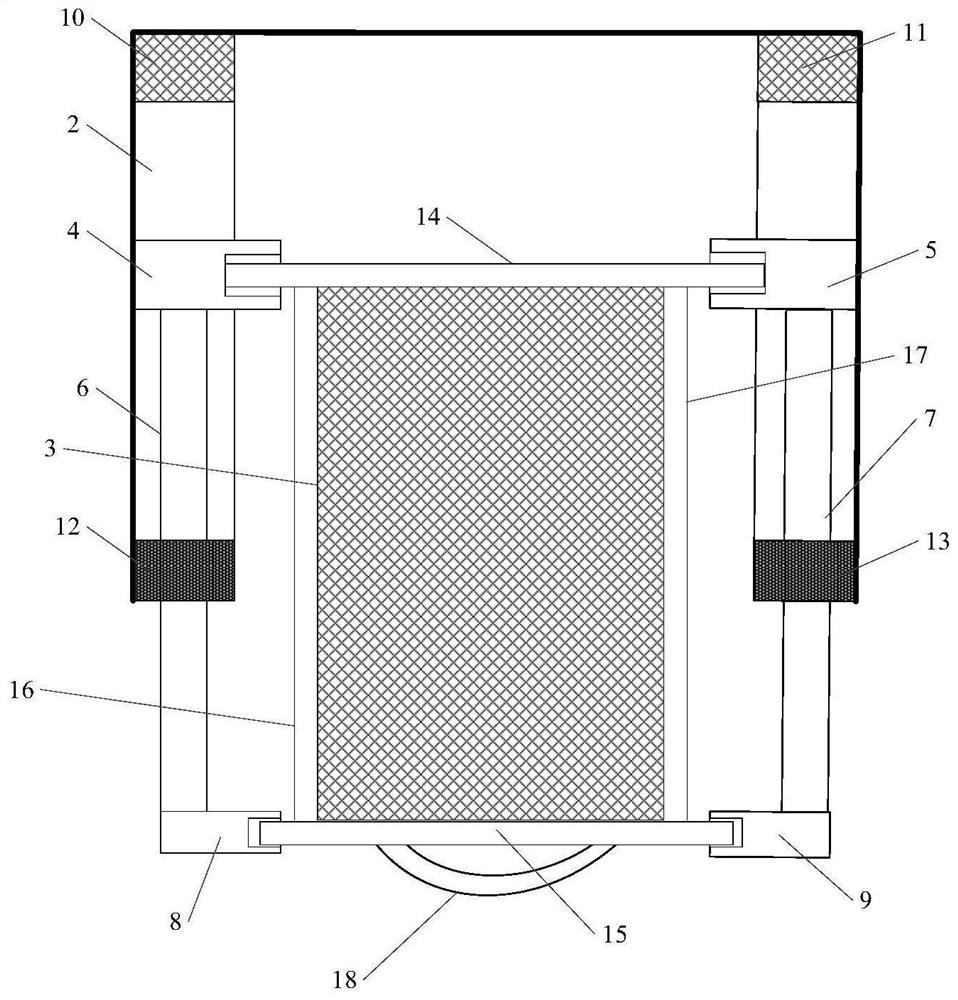
[0065] Please refer to Figure 3-Figure 4 , this embodiment provides a glass drying equipment for touch screen processing, the equipment includes a baking oven, the left and right inner walls of the oven are correspondingly provided with several pairs of chutes 2, and each pair of chutes corresponds to a glass drying oven. layer, the device also includes: several glass fixing structures, several first sliders 4, several second sliders 5, several first telescopic rods 6, several second telescopic rods 7, several first fixed blocks 8, several first telescopic rods Two fixed blocks 9, some first buffer blocks 10, some second buffer blocks 11, some first stop blocks 12 and some second stop blocks 13, each glass baking layer corresponds to a glass fixing structure, and the glass Fixed structures include:

[0066] The first fixed rod 14, the second fixed rod 15, the first fastening belt 16, the second fastening belt 17 and the handle 18; the first fixed rod and the second fixed rod...

Embodiment 2

[0074] Please refer to Figure 5-Figure 6 , on the basis of Embodiment 1, the device in Embodiment 2 also includes:

[0075] Stepping motor 25, stepping motor controller, several racks 20, several cross bars 21, some first driving rods 22 and some second driving rods 23;

[0076] Each glass baking layer corresponds to a rack, each rack corresponds to a cross bar, each cross bar corresponds to a first drive rod and a second drive rod, one end of the rack is fixedly connected to the middle of the corresponding cross bar, The two ends of the cross bar are respectively connected to one end of the corresponding first driving rod and one end of the second driving rod, and the other end of the first driving rod passes through the rear wall of the oven and the corresponding first buffer block in sequence and connects with the corresponding first driving rod. A slide block is fixedly connected, and the other end of the second driving rod passes through the rear wall of the oven and th...

Embodiment 3

[0079] Please refer to Figure 7 , on the basis of Embodiment 1, the device in Embodiment 3 also includes:

[0080] Glass unloading structure, the glass unloading structure includes a number of pulleys 26 evenly arranged horizontally, the horizontal centerlines of several pulleys coincide with the horizontal centerline of the glass conveyor belt 27, and the distance between the pulley closest to the glass conveyor belt and the glass conveyor belt The distance is less than one-fifth of the width of the glass, the distance between two adjacent pulleys is less than half of the width of the glass, and the gap between two adjacent pulleys corresponds to a glass fixing structure.

[0081] Wherein, the surface of the pulley is provided with a protective pad. The protective pad is a rubber pad or a sponge pad. The pulley is connected with the second rotating shaft, and the second rotating shaft can be installed and fixed through the bracket.

[0082] Please refer to Figure 15-Fig...


PUM


Abstract

The invention discloses a glass drying equipment and glass drying method for touch screen processing, and relates to the field of touch screen processing and manufacturing equipment. Each pair of chute corresponds to a glass baking layer, and the equipment also includes: several glass fixing structures, some first slide blocks, some second slide blocks, some first telescopic rods, some second telescopic rods, several first fixed block, several second fixed blocks, several first buffer blocks, several second buffer blocks, several first stop blocks and several second stop blocks, and each glass baking layer corresponds to a glass fixing structure, so as to realize the screen printing back glass Safe handling, and it is not easy to slip during the handling process, and it is not easy to scratch the silk screen pattern during the handling process, and it is not easy to scratch the glass when the glass enters and exits the baking oven, which improves the yield rate of glass baking.

Description

technical field [0001] The invention relates to the field of touch screen processing and manufacturing, in particular to glass drying equipment and a glass drying method for touch screen processing. Background technique [0002] The glass needs to be dried after silk screen printing, and then transported to the cutting machine for cutting. After cutting, the function test is carried out, such as figure 1 As shown, the existing oven such as figure 2 As shown, 1 is the baking oven, 2 is the chute, and 3 is the glass. [0003] The large piece of glass after silk screen printing is relatively large, usually 1m×1m in size, large in size and heavy in weight. It is not easy to put the large piece of glass into the oven and take it out of the oven. The traditional way is for workers to wear gloves to put in and take it out. In the process of using gloves to carry the glass, the glass is slippery and easy to slip and damage, and the pattern printed on the glass is easy to be damag...

Claims


Application Information

Patent Timeline
Patent Type & Authority Patents(China)
IPC IPC(8): B41F15/08B41F15/12B65G49/06C03B33/02C03B35/14C03C23/00
CPCB41F15/08B41F15/12B65G49/061C03B33/02C03B35/14C03C23/0085Y02P40/57
Inventor 李英
Owner GANZHOU LIDE ELECTRONICS CO LTD
Why Eureka
Try Eureka