
Constant-pressure liquid automatic pouring machine

A filling machine and liquid technology, applied in liquid bottling, liquid filling, liquid treatment, etc., can solve problems such as liquid qualitative change, and achieve the effect of occlusal fastening

Inactive Publication Date: 2020-09-01
陈华
View PDF13 Cites 0 Cited by
  • Summary
  • Abstract
  • Description
  • Claims
  • Application Information

AI Technical Summary

Problems solved by technology

[0002] In the process of liquid production and packaging, it is filled by a filling machine. In order to ensure the accuracy of filling, the existing automatic liquid filling machine directly inserts the filling head into the bottle, thus ensuring the filling process During the process, the liquid will not spill out, and the direct extension of the filling head into the bottle will cause impurities or even bacteria attached to the outer wall of the filling head to be brought into the bottle, resulting in a qualitative change in the liquid in the bottle

Method used


Image

  • Constant-pressure liquid automatic pouring machine
  • Constant-pressure liquid automatic pouring machine
  • Constant-pressure liquid automatic pouring machine

Examples


Embodiment 1

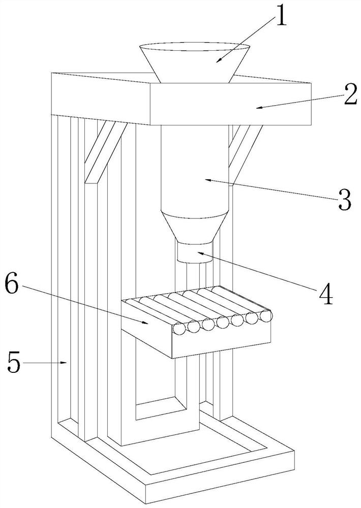
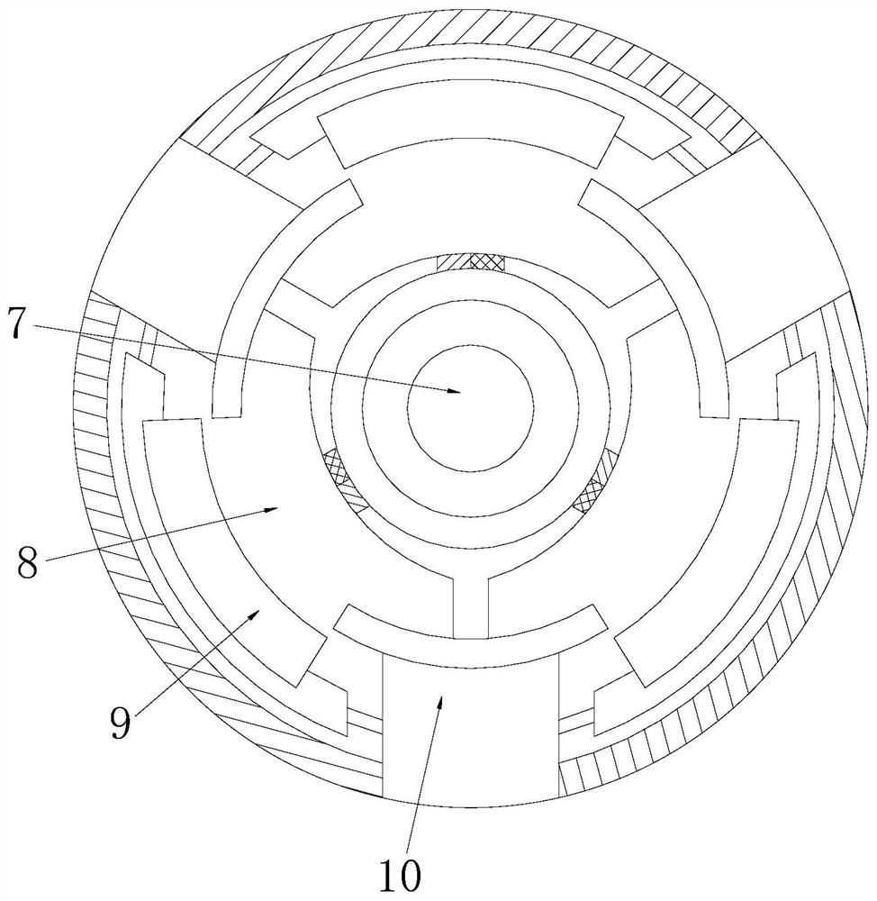
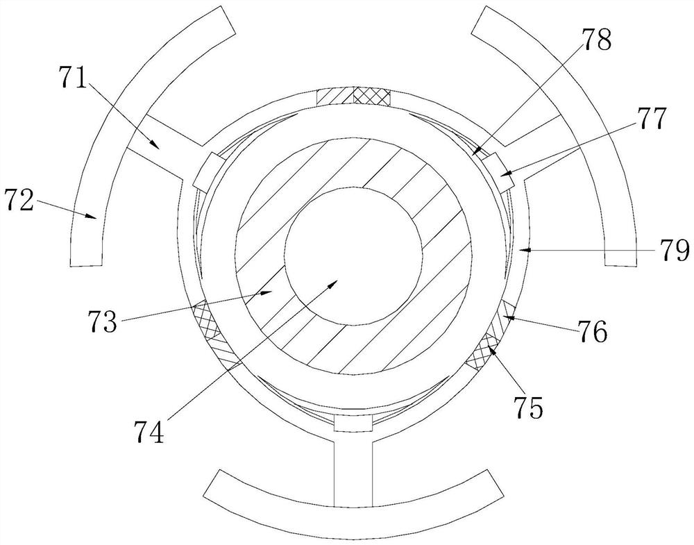
[0026] see Figure 1-Figure 6 , the present invention provides an automatic filling machine for normal-pressure liquids, the structure of which includes a hopper 1, an upper plate 2, a liquid storage chamber 3, an adapter 4, a fixing frame 5, and a workbench 6, and the hopper 1 is arranged on the upper layer On the top of the plate 2, the feeding bucket 1 communicates with the liquid storage cavity 3 through the upper plate 2, the liquid storage cavity 3 is installed in the south direction of the upper plate 2, the fixed frame 5 is mechanically welded with the workbench 6, and the fixed The frame 5 is fixedly connected with the upper plate 2, the workbench 6 is installed in the south direction of the connector 4, and the connector 4 communicates with the liquid storage chamber 3;

[0027] The adapter 4 is composed of a matching head 7, a fitting cavity 8, a connecting block 9, and a fixing block 10. block 10 , the connecting block 9 and the fixing block 10 are distributed alt...

Embodiment 2

[0037] see Figure 1-Figure 3 , the present invention provides an automatic filling machine for normal-pressure liquids, the structure of which includes a hopper 1, an upper plate 2, a liquid storage chamber 3, an adapter 4, a fixing frame 5, and a workbench 6, and the hopper 1 is arranged on the upper layer On the top of the plate 2, the feeding bucket 1 communicates with the liquid storage cavity 3 through the upper plate 2, the liquid storage cavity 3 is installed in the south direction of the upper plate 2, the fixed frame 5 is mechanically welded with the workbench 6, and the fixed The frame 5 is fixedly connected with the upper plate 2, the workbench 6 is installed in the south direction of the adapter 4, and the adapter 4 communicates with the liquid storage chamber 3; the adapter 4 is composed of a matching head 7, a fitting chamber 8, The connecting block 9 and the fixing block 10 are formed, the matching head 7 is located in the center of the fitting cavity 8, and th...


PUM


Abstract

The invention discloses a constant-pressure liquid automatic pouring machine. The constant-pressure liquid automatic pouring machine structurally comprises a feeding hopper, an upper-layer plate, a liquid storage cavity, a joint head, a fixing frame and a worktable. The feeding hopper is arranged on the top of the upper-layer plate and communicates with the liquid storage cavity through the upper-layer plate. The liquid storage cavity is formed in the due south direction of the upper-layer plate. The automatic pouring machine has the beneficial effects that due to the fact that an embedded block on the joint block makes contact with a bottle opening, a rotating roller rotates so that the embedded block can be matched with the bottle opening in size, a tooth plate and an engaged plate on the embedded block are matched so that the friction force between the bottle opening and the embedded block can become enlarged, the engagement between the bottle opening and the embedded block is firmer, in addition, a pouring channel is fixed above the bottle opening, three surrounding plates are used for wrapping the pouring channel, the position of the pouring channel is limited in a cavity defined by the three surrounding plates all the time, and therefore when pouring of the pouring channel is conducted, the pouring channel can be suspended and in butt joint with the bottle opening for pouring.

Description

technical field [0001] The invention relates to the field of filling machines, in particular to an automatic filling machine for normal-pressure liquids. Background technique [0002] In the process of liquid production and packaging, it is filled by a filling machine. In order to ensure the accuracy of filling, the existing automatic liquid filling machine directly inserts the filling head into the bottle, thus ensuring the filling process During the process, the liquid will not spill out, and the direct insertion of the filling head into the bottle will cause impurities or even bacteria attached to the outer wall of the filling head to be brought into the bottle, resulting in a qualitative change in the liquid in the bottle. Contents of the invention [0003] Aiming at the deficiencies of the prior art, the present invention is realized through the following technical solutions: an automatic filling machine for normal-pressure liquids, the structure of which includes an ...

Claims


Application Information

Patent Timeline
Patent Type & Authority Applications(China)
IPC IPC(8): B67C3/26B67C3/24B67C3/04
CPCB67C3/04B67C3/24B67C3/26
Inventor 陈华
Owner 陈华
Learn More