A kind of lightning protection radome sandwich structure

A sandwich structure and lightning protection technology, which is applied in the connection of antenna grounding switch structure, antenna, antenna parts, etc., can solve the problems of poor protection effect, difficult maintenance, ablation and falling off, etc., and achieves easy implementation, simple structure, high The effect of structural strength

Active Publication Date: 2021-01-19
CHINA SHIP DEV & DESIGN CENT
View PDF9 Cites 0 Cited by
  • Summary
  • Abstract
  • Description
  • Claims
  • Application Information

AI Technical Summary

Problems solved by technology

However, there is still a contradiction between the lightning protection effect and the deterioration of antenna performance (caused by the introduction of shunt strips) when using the above lightning protection technology. The number is small, and the impact on the antenna is correspondingly reduced, but its protection effect is also worse
At present, after the existing airborne radome lightning protection shunt strip is installed, the instantaneous electric field inside the radome is still very strong during the lightning strike, and the induced voltage between the radome wall and the antenna of the electronic equipment is extremely high and there is a risk of breakdown
In addition, conventional button-type shunt strips (especially conventional linear shunt strips) may ablate and fall off after multiple lightning strikes, making later maintenance difficult
[0005] Finally, the existing lightning rods (including shunt strips) are mainly used to solve the problem of protection against direct lightning strikes. They have basically no protective effect on the induced lightning generated during the downward current of direct lightning strikes. Vulnerable modules still pose a greater threat

Method used


Image

  • A kind of lightning protection radome sandwich structure
  • A kind of lightning protection radome sandwich structure
  • A kind of lightning protection radome sandwich structure

Examples


Embodiment Construction

[0024] In order to make the object, technical solution and advantages of the present invention clearer, the present invention will be further described in detail below in conjunction with the accompanying drawings and embodiments. It should be understood that the specific embodiments described here are only used to explain the present invention, not to limit the present invention.

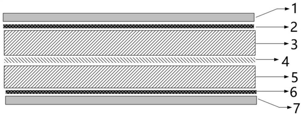
[0025] The lightning protection radome sandwich structure according to the embodiment of the present invention comprises a first skin layer 1 arranged at the top and a second skin layer 7 arranged at the bottom, and the gap between the first skin layer 1 and the second skin layer 7 is from top to bottom The first capacitive frequency selection layer 2, the first dielectric layer 3, the inductive shunt network layer 4, the second dielectric layer 5, and the second capacitive frequency selection layer 6 are arranged in sequence; the seven layers are in a close layered structure ;in:

[0026] The top...


PUM


Abstract

The invention discloses a lightning protection radome sandwich structure, which comprises a first skin layer arranged at the top and a second skin layer arranged at the bottom, and is characterized inthat a first capacitive frequency selection layer, a first dielectric layer, an inductive shunt network layer, a second dielectric layer and a second capacitive frequency selection layer are sequentially arranged between the first skin layer and the second skin layer from top to bottom; and the seven layers are of a tightly-attached layered structure. A lightning receiving column, a first skin layer, a first capacitive frequency selection layer and a first dielectric layer are arranged at the top of the lightning protection radome sandwich structure, a through hole is formed in the first dielectric layer, and copper foil paper is arranged on the inductive shunt network layer; the lightning receiving column successively passes through the first skin layer on the surface of the lightning protection radome sandwich structure, the first capacitive frequency selection layer, and the through hole on the first dielectric layer, and is connected with the copper foil paper on the inductive shunt network layer. According to the invention, the radiation performance of the antenna is not influenced, the lightning pulse field intensity inside the antenna cover sandwich structure under lightning impulse can be obviously reduced, and the lightning protection radome sandwich structure has the protection capabilities of direct lightning and inductive lightning.

Description

technical field [0001] The invention relates to the technical field of functional electromagnetic materials, in particular to a sandwich structure of a lightning protection radome. Background technique [0002] Restricted by the general layout conditions of the ship, its lightning protection design usually adopts the scheme of installing one (or more) lightning rods on the top of the mast. Since the size of the ship can reach hundreds of meters, the coverage area of ​​a single lightning rod is limited, and it is impossible to protect all the important equipment of the whole ship (especially the antenna of electronic equipment, etc.). In addition, according to foreign statistical data, the protection effect of lightning rods installed on land buildings is about 80%, while the lightning rods installed on sea buildings, due to the high humidity, heavy salt fog and fast wind speed on the sea surface, the same Its protection effect of lightning rod is only 50%~60% on land. Ther...

Claims


Application Information

Patent Timeline
Patent Type & Authority Patents(China)
IPC IPC(8): H01Q1/42H01Q1/50H01Q1/28H01Q1/34
CPCH01Q1/285H01Q1/34H01Q1/422H01Q1/50
Inventor 邓峰陈亮伍茂松陈立杰丁凡
Owner CHINA SHIP DEV & DESIGN CENT
Why Eureka
Try Eureka