Device for cleaning glass curtain wall
A glass curtain wall and cleaning mechanism technology, which is applied in the application, cleaning machinery, cleaning equipment, etc., can solve the problem of large manual labor for glass curtain walls, and achieve the effect of less labor and time saving
- Summary
- Abstract
- Description
- Claims
- Application Information
AI Technical Summary
Problems solved by technology
Method used
Image
Examples
Embodiment 1
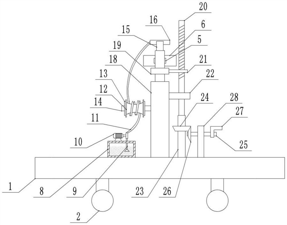
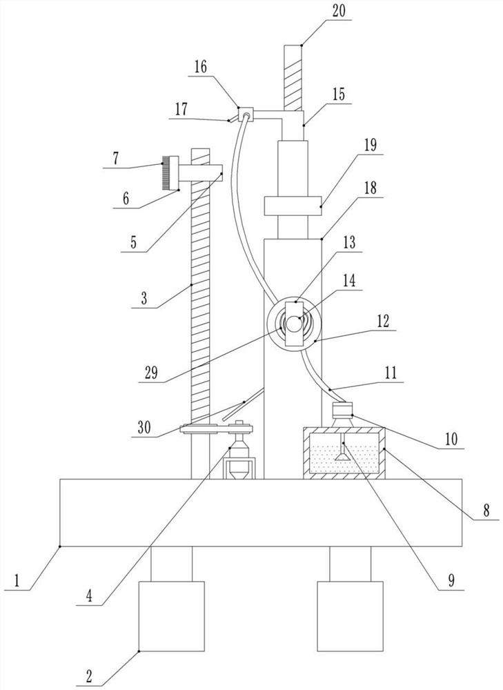
[0023] Such as figure 1 and figure 2 Shown: a device for cleaning glass curtain walls, including a base 1 and a cleaning mechanism. The cleaning mechanism includes a reciprocating screw 3 and a motor 4 with an output shaft. The bottom end of the reciprocating screw 3 and the top end of the base 1 pass through a bearing Rotational connection, the motor 4 is fixed on the top of the base 1, the reciprocating screw 3 and the output shaft of the motor 4 are equipped with pulleys, the two pulleys are connected by belt transmission, and the reciprocating screw 3 is threadedly connected with the first slider 5. A brush plate 6 is fixed on the first slider 5, bristles 7 are fixed on the brush plate 6, and four rollers 2 are evenly distributed on the bottom of the base 1.
[0024] The implementation mode of embodiment 1 is: when the glass curtain wall needs to be cleaned, the staff first moves the device to the position for cleaning the glass curtain wall, then the staff sprays water ...
Embodiment 2
[0026] Such as figure 1 and figure 2Shown: the difference between Embodiment 2 and Embodiment 1 is that a device for cleaning glass curtain walls also includes a water spray mechanism and a water retaining plate 30 for the motor 4 to retain water, and the water spray mechanism includes a telescopic rod 18, a water tank 8. The water pump 10, the L-shaped bracket 15 and the drive unit used to drive the telescopic rod 18 to expand and contract. The bottom end of the telescopic rod 18 is fixed on the top of the base 1. The telescopic rod 18 is arranged opposite to the reciprocating screw 3. The drive unit includes a first Rotating shaft 23, the second rotating shaft 25 and fixed plate 28, the top end of the first rotating shaft 23 and the top of base 1 are rotatably connected by bearing, the top of the first rotating shaft 23 is fixedly connected with screw mandrel 20, and the screw mandrel 20 is threadedly connected with the second Slider 21, the flexible end of telescopic rod ...
Embodiment 3
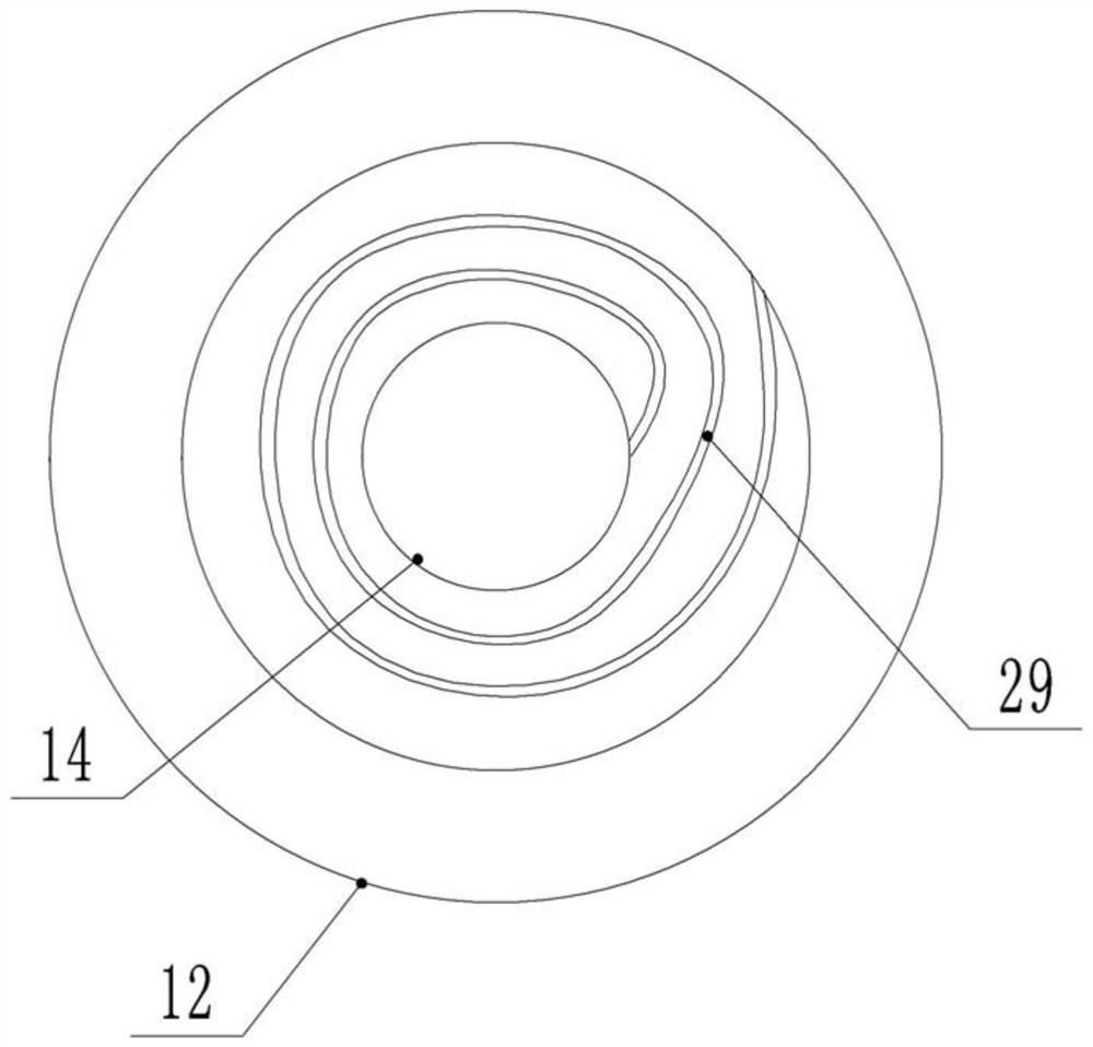
[0032] Such as Figure 1-Figure 3 As shown, the difference between embodiment 3 and embodiment 2 is that the water spray mechanism also includes a rewinding unit for rewinding the water outlet pipe 11, the rewinding unit includes a winding wheel 12 and a scroll spring 29, and the fixed end of the telescopic rod 18 is fixedly arranged. There is a support rod 14, on which two limit plates 13 are fixed, and the winding wheel 12 is sleeved on the support rod 14 between the two limit plates 13, and the winding wheel 12 can rotate freely on the support rod 14 The scroll spring 29 is located between the support rod 14 and the winding wheel 12, one end of the scroll spring 29 is fixedly connected to the support rod 14, the other end of the scroll spring 29 is fixedly connected to the winding wheel 12, and one end of the outlet pipe 11 is connected to the winding wheel 12. The water outlet end of the water pump 10 is connected, and the other end of the water outlet pipe 11 is wound on ...
PUM
 Abstract
Description
Claims
Application Information
 - R&D
- Intellectual Property
- Life Sciences
- Materials
- Tech Scout
- Unparalleled Data Quality
- Higher Quality Content
- 60% Fewer Hallucinations
Browse by: Latest US Patents, China's latest patents, Technical Efficacy Thesaurus, Application Domain, Technology Topic, Popular Technical Reports.
© 2025 PatSnap. All rights reserved.Legal|Privacy policy|Modern Slavery Act Transparency Statement|Sitemap|About US| Contact US: help@patsnap.com


