Eureka AIR delivers breakthrough ideas for toughest innovation challenges, trusted by R&D personnel around the world.

Claw replacement mechanism automatically correcting transverse deviations and mechanical hand equipment

A horizontal deviation and automatic technology, which is applied in the field of mechanical devices, can solve the problem of short loading and unloading of manipulator equipment, and achieve the effects of short loading and unloading time, high applicability, and low control precision requirements

Pending Publication Date: 2020-09-04
广州富港生活智能科技有限公司
View PDF0 Cites 0 Cited by
  • Summary
  • Abstract
  • Description
  • Claims
  • Application Information

AI Technical Summary

Problems solved by technology

[0003] The technical problem to be solved by the present invention is how to make the manipulator equipment loading and unloading time-consuming

Method used


Image

  • Claw replacement mechanism automatically correcting transverse deviations and mechanical hand equipment
  • Claw replacement mechanism automatically correcting transverse deviations and mechanical hand equipment
  • Claw replacement mechanism automatically correcting transverse deviations and mechanical hand equipment

Examples


Embodiment 1

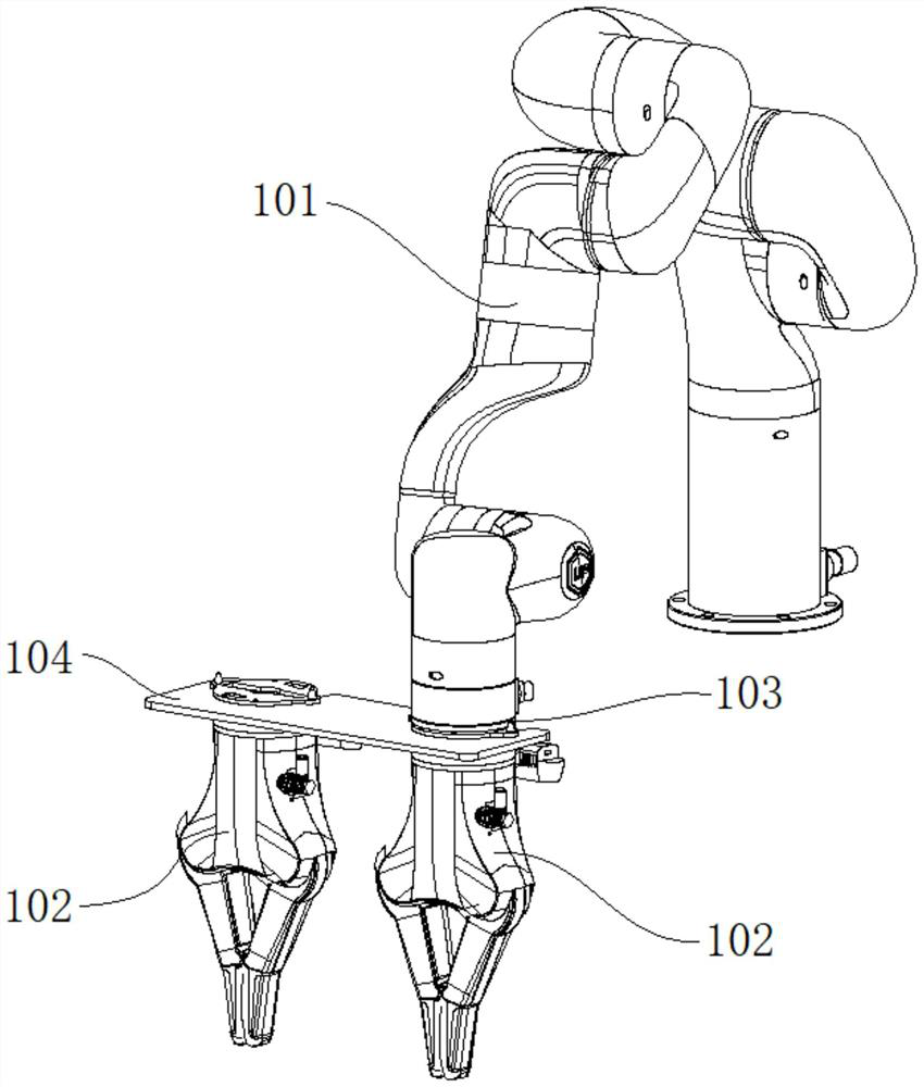
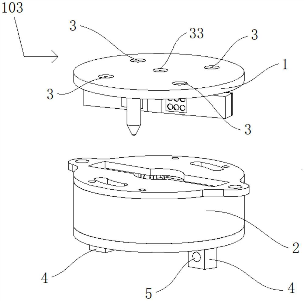
[0033] Robotic equipment such as figure 1 As shown, it includes a robotic arm 101 and a robotic claw 102 for grasping objects. The robotic claw 102 to be used is mounted on the robotic arm 101 using a claw changing mechanism 103, so that the robotic arm 101 can drive the robotic claw 102 to move, wherein the claw is changed. The mechanism 103 includes a jaw change aid 104 on which the mechanical jaws 102 not in use are placed. like figure 2 As shown, the claw changing mechanism 103 includes two connecting pieces, namely the arm connecting piece 1 and the claw connecting piece 2, wherein the arm connecting piece 1 is fixedly installed on the mechanical arm 101, and the claw connecting piece 2 is fixedly installed on the mechanical arm 101. Therefore, the arm connecting member 1 and the claw connecting member 2 are longitudinally close to each other to be assembled with each other, so that the mechanical claw 102 can be installed on the mechanical arm 101 . The specific insta...

Embodiment 2

[0043] Compared with the first embodiment, the present embodiment has the same mechanical arm 101 , the mechanical claw 102 and the claw changing auxiliary part 104 of the manipulator, but the structure of the claw changing mechanism 103 is different.

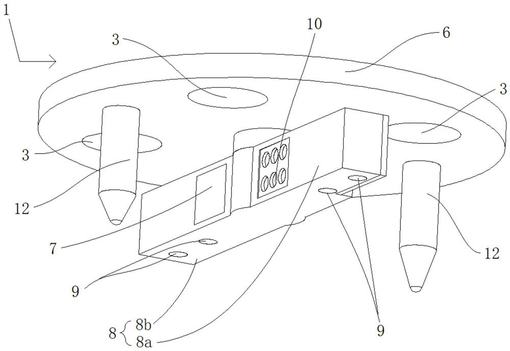
[0044] In this embodiment, the jaw changing mechanism 103 is as Figure 7 As shown, it includes an arm connector 1 and a claw connector 2, the arm connector 1 is fixedly installed on the mechanical arm 101, and the claw connector 2 is fixedly installed on the mechanical claw 102, wherein the arm connector 1 is as Figure 8 As shown, it includes a circular cover 6 and a shaft post 7 located at the center of the bottom of the cover body 6. The through hole 3 is opened on the cover body 6, and three clips protrude laterally from the side wall of the shaft post 7 near the bottom end. Connectors 26, 27, 28, these three card connectors 26, 27, 28 are distributed on the three equal positions of the shaft column 7, wherein, the bottom ...


PUM


Abstract

The invention provides a claw replacement mechanism automatically correcting transverse deviations. The claw replacement mechanism comprises two connecting pieces which are fixedly installed on a mechanical arm and a mechanical claw respectively. The two connecting pieces get close in a face-to-face mode in the longitudinal direction so as to be subjected to clamping connection. The first connecting piece comprises a first clamping connection block, the second connecting piece comprises a second clamping connection block, and the first connecting piece and the second connecting piece conduct transverse relative movement to enable the first clamping connection block and the second clamping connection block to be transversely moved and connected in a clamped mode. Transverse correction slopes are arranged in a clamping joint of the first clamping connection block and the second clamping connection block. The first connecting piece and the second connecting piece are guided by the transverse correction slopes in the process that the first connecting piece and the second connecting piece conduct transverse relative movement, and the positions of the first connecting piece and the second connecting piece are subjected to transverse relative fine adjustment so that the first clamping connection block and the second clamping connection block can align to each other. Even though the first clamping connection block and the second clamping connection block have the position deviations in the transverse direction, the first connecting piece and the second connecting piece can also besubjected to transverse relative fine adjustment by the transverse correction slopes in the clamping connection process so as to enable the first clamping connection block and the second clamping connection block to align to each other, and therefore the claw replacement mechanism is low in requirement for the control accuracy of mechanical hand equipment and high in applicability.

Description

technical field [0001] The invention relates to the technical field of mechanical devices, in particular to a claw changing mechanism and a manipulator device for automatically correcting lateral deviation. Background technique [0002] In order to improve production efficiency and competitiveness, many companies currently use advanced manipulator equipment to assist the production process. Manipulator equipment is a kind of action function that can imitate human hands and arms to grab, move objects or operate tools according to fixed procedures. The automatic operation device is mainly composed of a mechanical arm and a mechanical claw installed on the mechanical arm. In order to meet the production needs of different types of products, the manipulator equipment needs to be equipped with different manipulator claws. The traditional manipulator equipment uses screws to fix the manipulator claws on the manipulator arm. When the manipulator needs to be replaced, the screws are...

Claims


Application Information

Patent Timeline
Patent Type & Authority Applications(China)
IPC IPC(8): B25J15/04
CPCB25J15/0408B25J15/04
Inventor 傅峰峰江志强刘楚奇陈伟俊
Owner 广州富港生活智能科技有限公司
Why Eureka
Eureka Blog
Learn More