

Bulging tooling and clamping method for large-size thin-walled cylindrical parts
A thin-walled cylinder and large-size technology, which is applied in the direction of metal processing machinery parts, clamping, manufacturing tools, etc., to achieve the effects of convenient operation, labor saving, short loading and unloading time, and simple structure
Inactive Publication Date: 2019-10-01
XIAN AERONAUTICAL UNIV
View PDF5 Cites 0 Cited by
- Summary
- Abstract
- Description
- Claims
- Application Information
AI Technical Summary
Problems solved by technology
The purpose of the present invention is to provide a large-size thin-walled cylindrical part bulging tool, which solves the problem that the existing clamping tool cannot quickly and labor-savingly correct the deformed thin-walled cylindrical part blank into a cylindrical shape through clamping
Method used
View moreImage
Smart ImageViewing Examples

Examples
Embodiment Construction
Login to View More PUM
 Abstract
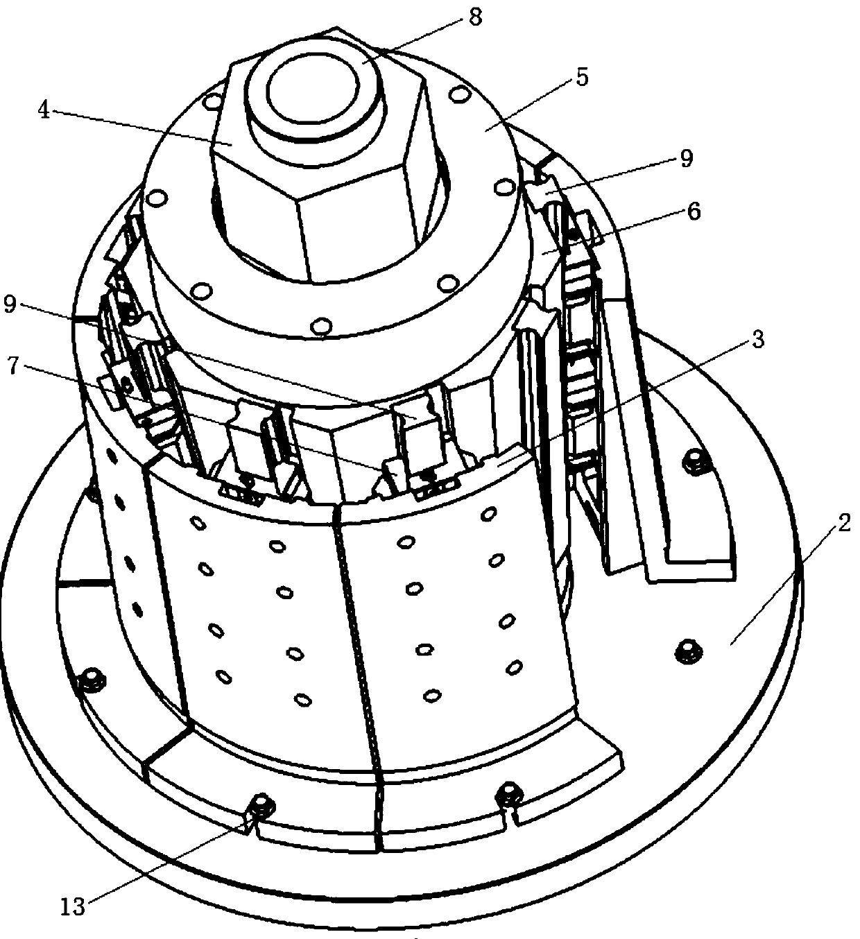
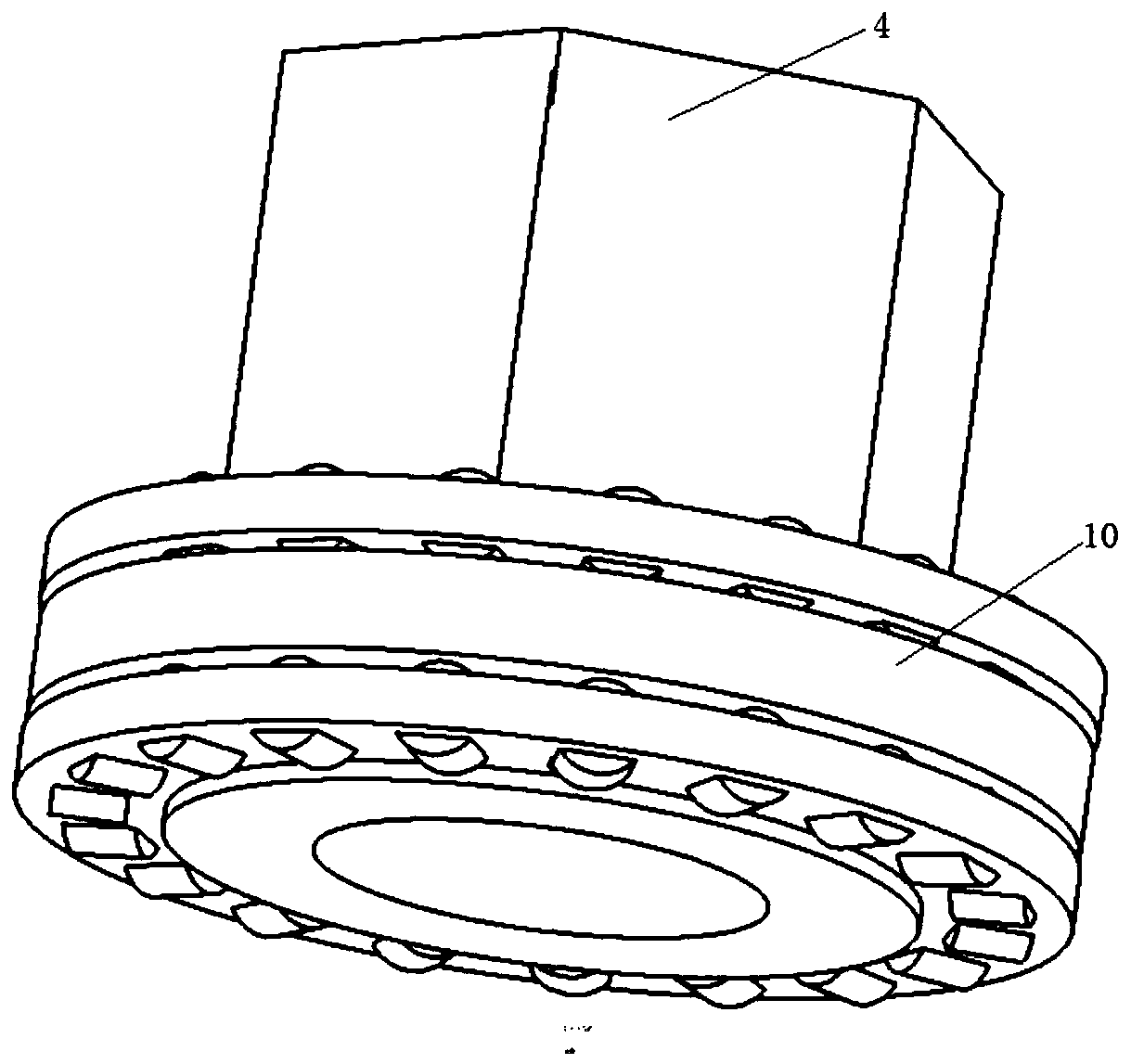
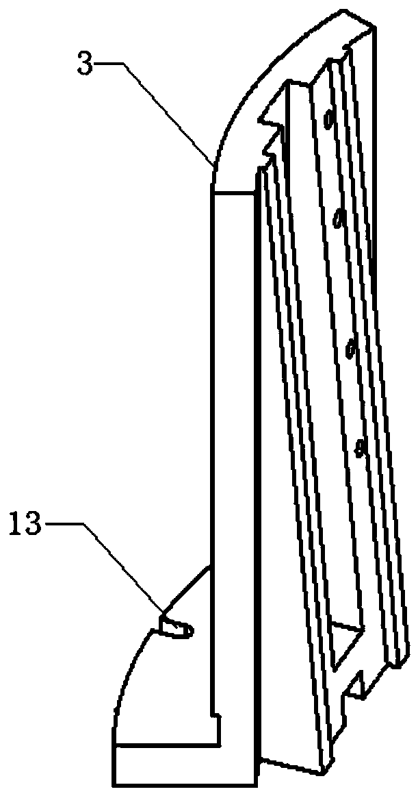
The invention discloses a large-sized thin-walled cylinder part bulging tool. The large-sized thin-walled cylinder part bulging tool comprises a base, a regularly-octagonal pyramid sleeve, eight bulging sections and a nut with a flange at the lower end. A fixed column with a thread at the upper end is vertically and fixedly arranged at the center of the base. The nut and the regularly-octagonal pyramid sleeve are embedded into the fixed column in sequence from top to bottom. A gland is fixedly connected with the regularly-octagonal pyramid sleeve. A rolling guide rail is arranged on each outercone face of the regularly-octagonal pyramid sleeve. Each bulging section is divided into a horizontal segment and a vertical segment. The horizontal segments are movably connected to the base. Sliding grooves matched with the rolling guide rails are formed the inner surfaces of the vertical segments. Sliding blocks are mounted in the sliding grooves. The invention further discloses a clamping method for the large-sized thin-walled cylinder part bulging tool. The clamping method comprises the following specific steps of mounting the tool, adjusting the regularly-octagonal pyramid sleeve to belocated on the upper portion, clamping a cylinder part, performing adjusting and measuring, performing outer circle machining and detaching the part. This large-sized thin-walled cylinder part bulging tool can efficiently and reliably clamp the large-sized thin-walled cylinder part and is high in clamping accuracy.
Description
technical field The invention belongs to the technical field of mechanical manufacturing, and in particular relates to a large-size thin-wall cylindrical part bulging tool, and also relates to a clamping method using the large-size thin-wall cylindrical part bulging tool. Background technique Large-size thin-walled cylindrical parts are one of the common parts in chemical machinery, aviation, aerospace and other products, and are often used as containers or product shells. Such parts will have requirements such as stiffness, strength, and corrosion resistance. For large-scale thin-walled cylindrical parts in aviation and aerospace, there are also requirements for weight reduction. Especially for large-sized (diameter greater than 500mm) and thin-walled (wall thickness less than 10mm) parts, the blank is usually welded or spinning, which has large deformation, poor precision, and large dispersion of deformation, which is irregular to find. The clamping method and tooling of...
Claims
Login to View More Application Information
Patent Timeline
 Patent Type & AuthorityPatents(China)
IPC IPC(8): B23Q3/06
Inventor郝红武
OwnerXIAN AERONAUTICAL UNIV