A Laser Shock Thin Plate Glue Rivet Composite Connection Method and Its Application

A technology of laser shock and composite connection, which is applied in chemical instruments and methods, lamination auxiliary operations, lamination, etc., can solve the problems of aggregated flow of adhesive between boards, difficulty in riveting applications, and interlocking embedding volume, etc. problems, to achieve the effect of ensuring continuous and uniform distribution, small stress gradient, and easy riveting

Active Publication Date: 2021-07-27
SHANDONG UNIV
View PDF2 Cites 0 Cited by
  • Summary
  • Abstract
  • Description
  • Claims
  • Application Information

AI Technical Summary

Problems solved by technology

However, the existing technology encounters difficulties in riveting thin plates. The primary reason is that the joint strength of traditional rivetless press riveting depends on the amount of interlocking insertion caused by the thick extrusion of the plate in the mold cavity and the upper plate on the neck of the joint. The thickness of the thin plate is difficult to achieve riveting application because it is difficult to produce sufficient thickness deformation and interlocking embedding; secondly, the severe extrusion of the plate in the mold cavity is easy to cause the adhesive between the plates to flow together, resulting in The layers are discontinuously distributed inside the joint and may create plastic pockets, further reducing the amount of "hard-fought" interlock embedment; again, it is difficult to control the thickness of the glue layer when the panels are glued by partial glue
Therefore, in the field of connecting thin plates, especially ultra-thin plates, traditional rivetless riveting and its technical combination with chemical bonding still face many difficulties

Method used


Image

  • A Laser Shock Thin Plate Glue Rivet Composite Connection Method and Its Application
  • A Laser Shock Thin Plate Glue Rivet Composite Connection Method and Its Application
  • A Laser Shock Thin Plate Glue Rivet Composite Connection Method and Its Application

Examples


no. 1 example

[0034] A thin-plate adhesive riveting compound connection method by laser shock, the laser beam adopts 700mJ YAG pulse laser, the pulse width is 8ns, the pulse frequency is 10Hz, and the laser beam diameter is 4mm.

[0035] The upper plate is a pure copper plate with a thickness of 0.03mm, and the lower plate is a pure aluminum plate with a thickness of 0.02mm.

[0036] The hole diameter of the holed mold used is 2.5mm.

[0037] The adhesive used was Henkel Teroson EP 5055.

[0038] Specific steps are as follows:

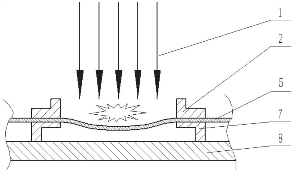
[0039] A. If figure 1 As shown, the lower plate 5 is placed on the mold 7 with a hole, and then clamped with the clamping device 2, and the pulsed laser beam 1 is used to impact the lower plate 5, so that the impact forming on the lower plate has a depth of 0.2mm. Then fill the pit with adhesive 6.

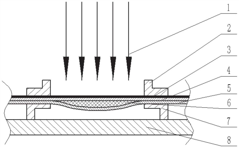
[0040] B. If figure 2 As shown, the upper surface of the upper plate 4 is coated with paraffin wax as the energy absorbing layer 3, and the upper plate 4 and the lo...

no. 2 example

[0044] A thin-plate adhesive riveting compound connection method by laser shock, the laser beam adopts 1000mJ YAG pulse laser, the pulse width is 8ns, the pulse frequency is 10Hz, and the laser beam diameter is 6mm.

[0045] The upper plate is a pure copper plate with a thickness of 0.03mm, and the lower plate is a pure copper plate with a thickness of 0.03mm.

[0046] The hole diameter of the holed mold used is 4mm.

[0047] Adhesive adopts HUITIAN 6011 one-component heat curing epoxy adhesive for structural bonding.

[0048] Specific steps are as follows:

[0049] A. If figure 1 As shown, the lower plate 5 is placed on the mold 7 with a hole, and then clamped with the clamping device 2, and the pulsed laser beam 1 is used to impact the bulging of the lower plate 5, so that the impact forming on the lower plate has a depth of 0.3mm. Then fill the pit with adhesive 6.

[0050] B. If figure 2 As shown, the upper surface of the upper plate 4 is coated with black paint as t...

no. 3 example

[0054] A laser-shock thin-plate adhesive riveting compound connection method, the laser beam adopts 1200mJ YAG pulse laser, the pulse width is 8ns, the pulse frequency is 10Hz, and the laser beam diameter is 6mm.

[0055] The upper plate is a pure copper plate with a thickness of 0.05mm, and the lower plate is a pure aluminum plate with a thickness of 0.05mm.

[0056] The hole diameter of the holed mold used is 4 mm.

[0057] The adhesive used was Henkel Teroson EP 5055.

[0058] Specific steps are as follows:

[0059] A. If figure 1 As shown, the lower plate 5 is placed on the mold 7 with holes, and then clamped with the clamping device 2, and the pulsed laser beam 1 is used to impact the lower plate 5, so that the impact forming on the lower plate has a depth of 0.6mm. Then fill the pit with adhesive 6.

[0060] B. If figure 2 As shown, the upper surface of the upper plate 4 is coated with paraffin wax as the energy absorbing layer 3, and the upper plate 4 and the lowe...


PUM

PropertyMeasurementUnit
thicknessaaaaaaaaaa
thicknessaaaaaaaaaa
thicknessaaaaaaaaaa

Abstract

The invention relates to the technical field of thin plate connection, in particular to a laser impacted thin plate glue riveting composite connection method and application thereof. The method includes the following steps: (1) bulging by laser shock to make the lower board produce pits, then injecting adhesive into the pits, stacking the upper board and the lower board, and coating the surface of the upper board. The energy absorbing agent layer and the constraining layer are covered, and laser impact riveting is performed again to obtain a glue riveting composite joint. (2) The adhesive riveting composite joint is allowed to stand at room temperature or placed in a furnace for heating and heat preservation to solidify the adhesive. The invention firstly uses the laser shock bulging method to make micro-pits to form a glue riveting composite connection with an evenly distributed glue layer and an interlocking embedded structure between two layers of plates, and finally the glue in the joint is cured, and finally The adhesive riveted composite joint with high strength, good sealing performance and excellent corrosion resistance is obtained.

Description

technical field [0001] The invention relates to the technical field of thin plate connection, in particular to a thin plate glue riveting compound connection method and its application by laser shock. Background technique [0002] The information disclosed in this background section is only intended to increase the understanding of the general background of the present invention, and is not necessarily taken as an acknowledgment or any form of suggestion that the information constitutes the prior art already known to those skilled in the art. [0003] Common plate joining methods include riveting, welding, gluing, etc., which are widely used in automobiles, aircrafts, rail transit and other fields. The weakness of a single connection method is obvious. For example, the welding method is characterized by high connection strength, but due to the different melting points of different materials, it encounters difficulties in connecting dissimilar plates; adhesive bonding can be ...

Claims


Application Information

Patent Timeline
Patent Type & Authority Patents(China)
IPC IPC(8): B32B37/12B32B38/00
CPCB32B37/12B32B38/0008B32B2037/243B32B2310/0843
Inventor 季忠王逸群卢国鑫刘韧郑超
Owner SHANDONG UNIV
Why Eureka
Try Eureka