
Portable high-speed thermal printer

A technology of thermal printers and printers, applied in printing devices, printing, etc., can solve the problems of poor dust-proof effect, dust impurities entering, affecting the overall use, etc., to ensure printing performance, ensure sealing and dust-proof effects, and be easy to use Effect

Active Publication Date: 2020-09-04
ZHENYI ELECTRONICS SHENZHEN
View PDF10 Cites 1 Cited by
  • Summary
  • Abstract
  • Description
  • Claims
  • Application Information

AI Technical Summary

Problems solved by technology

[0003] Although the existing thermal printers are easy to carry when in use, the overall dustproof effect of the existing thermal printers is poor. overall use

Method used


Image

  • Portable high-speed thermal printer
  • Portable high-speed thermal printer
  • Portable high-speed thermal printer

Examples


Embodiment 1

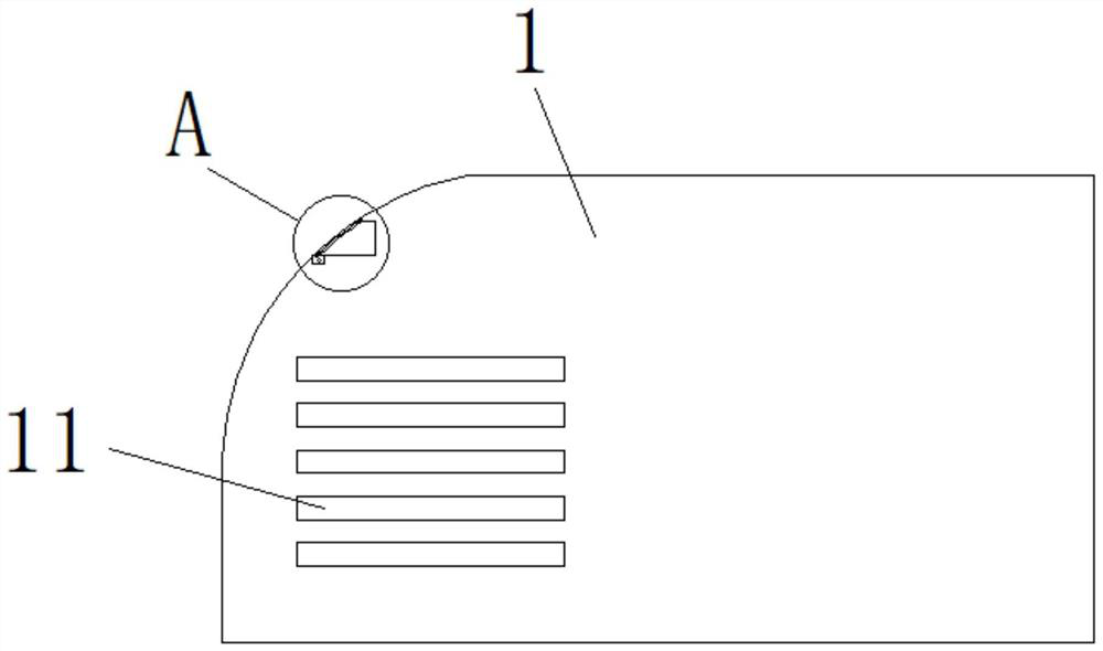
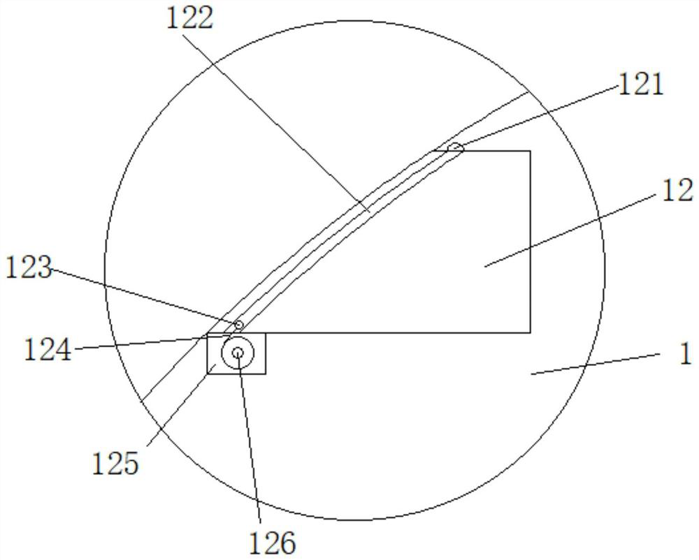
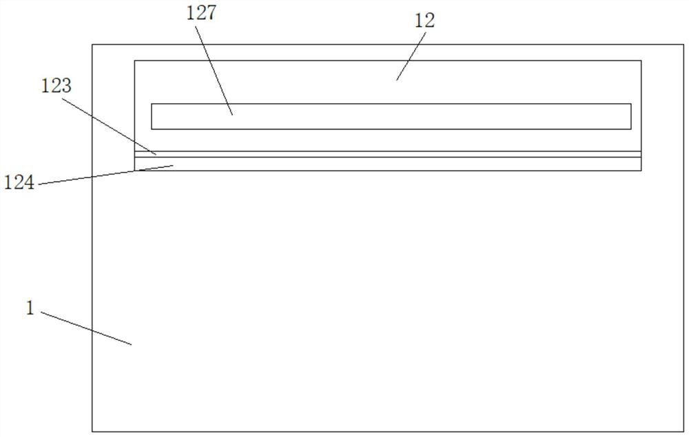
[0024] see Figure 1-4 , a portable high-speed thermal printer, comprising a printer main body 1, a print outlet 127 arranged on the printer main body 1, an outlet slot 12 is arranged on the printer main body 1 at the print outlet 127, and all print outlets outside the print outlet 127 The two side walls of the outlet groove 12 are provided with symmetrically distributed chute 122, and a sealing rod 123 for sliding connection is arranged between the chute 122. The printer main body 1 at the bottom of the outlet groove 12 is provided with an outlet groove 12 is connected with the adjustment groove 125, the adjustment groove 125 is provided with a rotatably connected adjustment roller 126, and the adjustment roller 126 is provided with a sealing tape 124 that is evenly wound and used for sealing the outlet groove 12, and the sealing tape The extended end of 124 is connected and fixed with the sealing rod 123. There are a plurality of symmetrically distributed heat dissipation ho...


PUM


Abstract

The invention belongs to the technical field of thermal printers, and particularly relates to a portable high-speed thermal printer. The portable high-speed thermal printer comprises a printer body, aprinting outlet and an outlet groove. Symmetrically-distributed sliding grooves are formed in the two side walls of the outlet groove, and a sealing rod in sliding connection is arranged between thesliding grooves. Multiple symmetrically-distributed heat radiation holes are formed in the two sides of the printer body, heat radiation grooves are formed in the positions, located at the upper endsand the lower ends of the heat radiation holes, of the printer body, dustproof plates which are in sliding connection and are used for sealing the heat radiation holes are arranged in the heat radiation grooves, and connected connecting rods are arranged between the dustproof plates. A communicating hole is formed in the heat radiation groove located at the uppermost end, a connecting wire is arranged in the communicating hole, one end of the connecting wire is fixedly connected with the end of the dustproof plate in the corresponding heat radiation groove, and the other end of the connectingwire is fixedly connected with the sealing rod in the sliding grooves. The overall sealing and dustproof effect generated when the printer is not used is guaranteed, meanwhile, the heat radiation effect generated when the printer is not used is not influenced, and use is convenient.

Description

technical field [0001] The invention belongs to the technical field of thermal printers, in particular to a portable high-speed thermal printer. Background technique [0002] The working principle of a thermal printer is that a semiconductor heating element is installed on the print head. After the print head is heated and contacts the thermal printing paper, the required pattern can be printed out. Its principle is similar to that of a thermal fax machine. The image is created by applying heat, which creates a chemical reaction in the film. This thermal printer chemical reaction is carried out at a certain temperature. High temperatures accelerate this chemical reaction. When the temperature is lower than 60°C, it takes quite a long time, even several years, for the paper to become dark; and when the temperature is 200°C, this reaction will be completed within a few microseconds. [0003] Although the existing thermal printers are easy to carry when in use, the overall d...

Claims


Application Information

Patent Timeline
IPC IPC(8): B41J29/377B41J29/13B41J2/32
CPCB41J29/377B41J29/13B41J2/32
Inventor 王泽灵
Owner ZHENYI ELECTRONICS SHENZHEN
Learn More