Candy packaging machine

A packaging machine and candy technology, applied in the field of candy packaging, can solve the problems of inability to package box decoration and packaging, and achieve the effect of improving printing packaging efficiency and fast printing packaging.

Inactive Publication Date: 2020-09-04
江永网农电子商务有限公司
View PDF15 Cites 3 Cited by
  • Summary
  • Abstract
  • Description
  • Claims
  • Application Information

AI Technical Summary

Problems solved by technology

But the box cannot be decorated and packaged

Method used


Image

  • Candy packaging machine
  • Candy packaging machine
  • Candy packaging machine

Examples


specific Embodiment approach 1

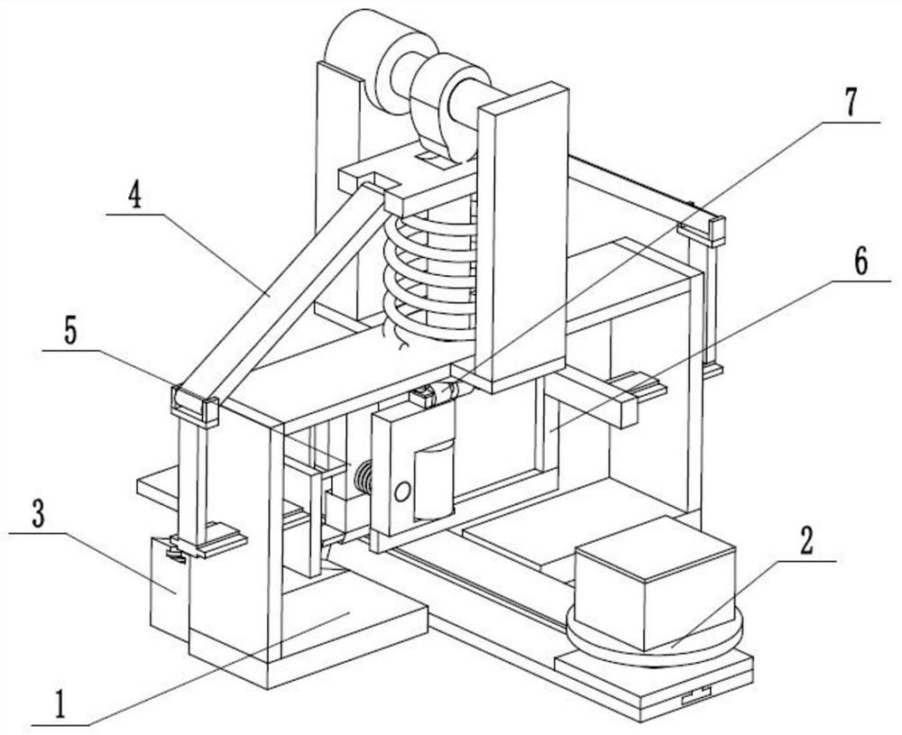
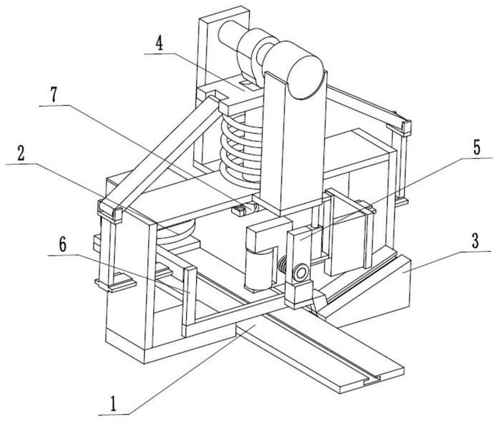
[0029] Such as Figure 1 to Figure 9 As shown, a candy packaging machine includes a packaging frame 1, a transport carrier 2, a limit ramp seat 3, a combined driver 4, a side packaging printer 5, an L-shaped driving rack 6 and an upper surface printer 7. The above-mentioned transport carrier 2 is horizontally slidably connected to the packaging frame 1, the transport carrier 2 is engaged with the L-shaped driving rack 6 for transmission, the limit ramp seat 3 is fixedly connected to the packaging frame 1, and the combined drive 4 is slidably connected In the packaging frame 1, the side packaging printer 5 and the L-shaped driving rack 6 are respectively fixedly connected to the two ends of the inner wall of the combination driver 4, and the side packaging printer 5 is slidably connected to the limit slope seat 3, and the upper end surface printer 7 is fixedly connected to the lower end of combination driver 4. Place the box to be printed and packaged on the transport carrier ...

specific Embodiment approach 2

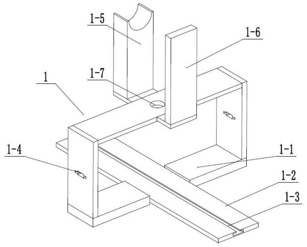
[0031] Such as Figure 1 to Figure 9As shown, this embodiment will further explain Embodiment 1. The packaging frame 1 includes a frame frame 1-1, a horizontal fixed slide plate 1-2, a horizontal chute 1-3, and two limiting inner chute 1 -4, motor fixing seat 1-5, fixed rotating seat 1-6 and center turning hole 1-7, horizontal fixed slide plate 1-2 is fixedly connected in the frame frame 1-1, and horizontal chute 1-3 runs through and is arranged on On the horizontally fixed slide plate 1-2, two limiting inner chute 1-4 respectively run through the two ends of the frame frame 1-1, and the motor fixing seat 1-5 and the fixed rotating seat 1-6 are fixedly connected on the On the upper end of the frame frame 1-1, the central turning hole 1-7 is arranged at the center of the upper end of the frame frame 1-1.

specific Embodiment approach 3

[0033] Such as Figure 1 to Figure 9 As shown, this embodiment will further illustrate the second embodiment. The transport carrier 2 includes an intermittent drive slide 2-1, a lower slider 2-2, a loading shaft 2-3, an engaging gear 2-4, Loading turntable 2-5 and fixed plug 2-6, the lower end of intermittent driving slide seat 2-1 is slidably connected in the transverse chute 1-3 through lower block 2-2, and load shaft 2-3 is rotationally connected in the intermittent On the drive slide 2-1, the connecting gear 2-4 and the loading turntable 2-5 are all fixedly connected on the loading rotating shaft 2-3, and the fixed plug 2-6 is fixedly connected on the loading rotating disk 2-5. The candy box to be printed and packaged is placed on the fixed insert 2-6; the drive intermittently drives the slide 2-1 to move in the horizontal fixed slide 1-2 through the lower slide 2-2 until the gear 2-4 is connected with the L-shaped drive The tooth bar 6 is in contact with each other and s...


PUM


Abstract

The invention relates to the field of candy packaging, in particular to a candy packaging machine. The candy packaging machine comprises a packaging rack, a conveying carrier seat, a limiting slope seat, a combined driver, a side face packaging printing device, an L-shaped driving rack and an upper end face printing device, wherein the conveying carrier seat is transversely connected to the packaging rack in a sliding mode, and the conveying carrier seat is in meshing transmission with the L-shaped driving rack; the limiting slope seat is fixedly connected to the packaging rack, the combined driver is slidably connected into the packaging rack, the side face packaging printing device and the L-shaped driving rack are fixedly connected to the two ends of the inner wall of the combined driver respectively, the side face packaging printing device is slidably connected to the limiting slope seat, and the upper end face printing device is fixedly connected to the lower end of the combined driver. The candy packaging machine disclosed by the invention has beneficial effects is used for packaging and printing which can be used for rapidly carrying out appointed placement on a packaging box; the packaging boxes can be rapidly printed and packaged in batches, and the printing and packaging efficiency is improved; and boxes with different shapes can be quickly printed and packaged.

Description

technical field [0001] The invention relates to the field of candy packaging, in particular to a candy packaging machine. Background technique [0002] Patent No. CN201610023250.6 discloses a candy packaging machine, comprising: a feeding device, which includes: a feeding port; a centrifugal disc, which is connected to the rotating rod and is located below the feeding port, and the centrifugal disc is provided with There are multiple feeding bayonets, the feeding bayonet is provided with a feeding bayonet piece that can adjust the size of the feeding bayonet; and a wall tube is arranged around the centrifugal disc, and the wall tube is provided There are discharge ports corresponding to the feeding bayonets one by one; a paper discharge device, which is arranged around the outside of the wall tube, is used to discharge the wrapping paper to cover the falling candy; and a heat sealing device, which is correspondingly provided on the Below the output unit. The candy packagin...

Claims


Application Information

Patent Timeline
Patent Type & Authority Applications(China)
IPC IPC(8): B65B25/00B65B61/02B65B61/26B41F17/26
CPCB41F17/26B65B25/005B65B61/025B65B61/26
Inventor 潘林军
Owner 江永网农电子商务有限公司
Why Eureka
Try Eureka