Control method and controller for 3D (three-dimension) printing and scanning

A technology of 3D printing and control method, applied in the field of control and control device for 3D printing scanning, can solve the problem of high precision, mechanical stress, fatigue strength, high deformation quantity, poor molding accuracy of parts, and poor surface finish and other problems, to achieve the effect of improving surface finish, improving contour accuracy, facilitating area division and printing and scanning

Active Publication Date: 2015-04-01
GUANGDONG HANBANG 3D TECH CO LTD
View PDF10 Cites 14 Cited by
  • Summary
  • Abstract
  • Description
  • Claims
  • Application Information

AI Technical Summary

Problems solved by technology

[0002] With the development of 3D printing technology, metal powder laser rapid prototyping direct manufacturing technology has become the focus of everyone's attention. Metal powder laser rapid prototyping has left everyone with a high, large and high-end image, but in the current situation, there are also some shortcomings, different sizes Parts with different shapes have poor molding accuracy, poor surface finish, inconsistent stress and deformation, and even serious deformations that cause collisions with powder scrapers and molding failures, such as molding surgical bone replacements, dental implant screws, etc. , anti-fatigue strength, and deformation are all very high. The existing technical solution is to set one parameter for the inner and outer contours of each layer of data, and another parameter setting for the inner filling area. The parameters include laser power, scanning speed, Jump speed, corner delay, jump delay, laser on delay and laser off delay, this simple distinction has made great progress compared to the earlier one-parameter molding, and the molding effect has been greatly improved , but still cannot meet the demanding application requirements

Method used


Image

  • Control method and controller for 3D (three-dimension) printing and scanning
  • Control method and controller for 3D (three-dimension) printing and scanning
  • Control method and controller for 3D (three-dimension) printing and scanning

Examples


Embodiment Construction

[0029] A further detailed description will be made below in conjunction with the accompanying drawings and embodiments of the present invention:

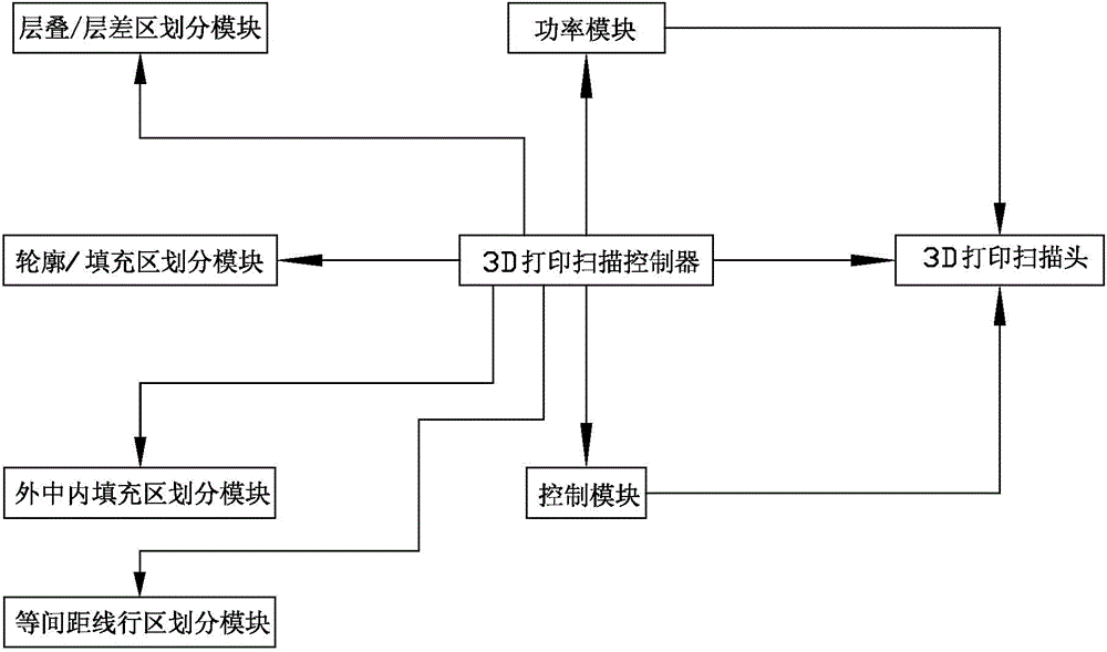
[0030] Such as figure 1 As shown, a control method for 3D printing scanning is characterized in that it includes the following steps:

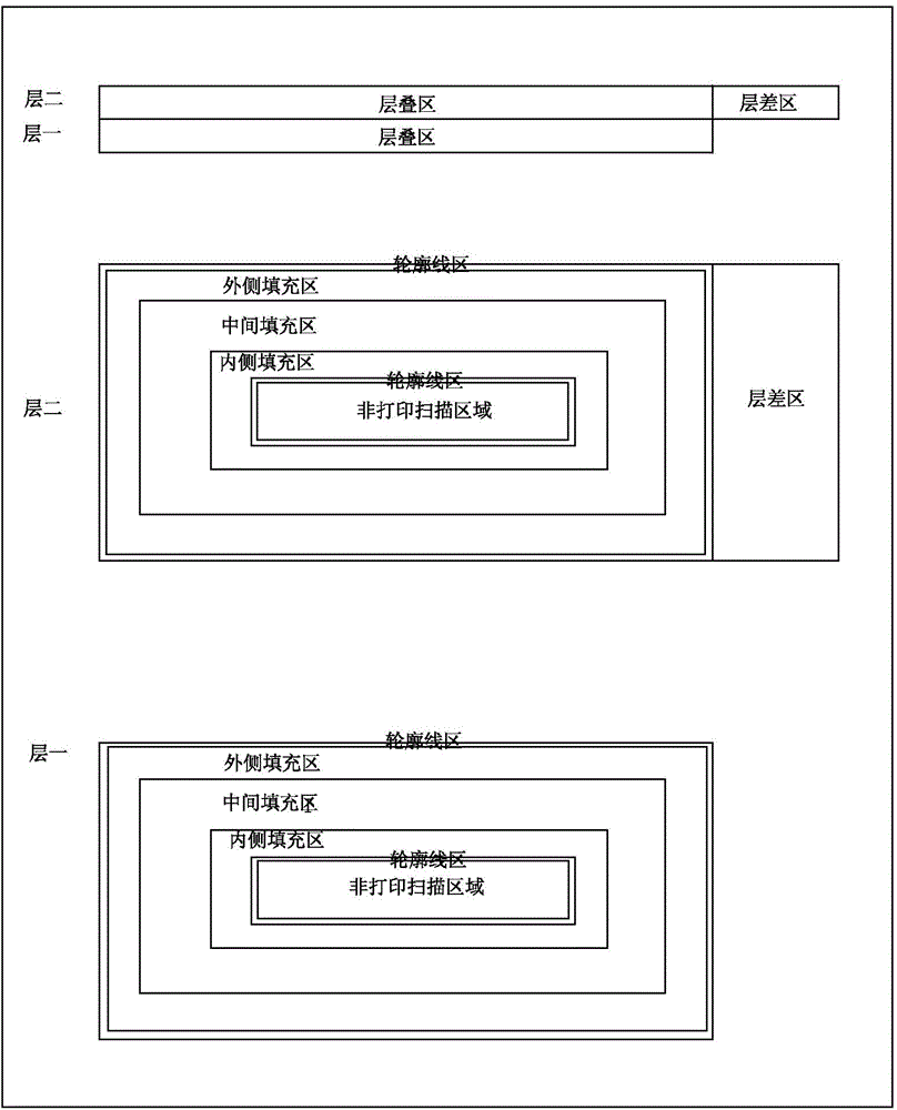
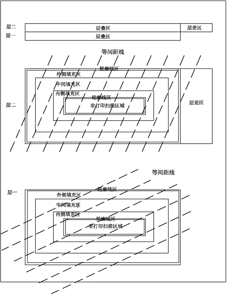
[0031] A. Comparing the area overlap of the upper and lower adjacent printing and scanning layers, the overlapping printing and scanning area in the two layers is divided into a stacking area, and the non-overlapping printing and scanning area is divided into a layer difference area. Among them, in the same printing and scanning layer, first Print and scan the layered area, and then print and scan the layered area, and relatively reduce the printing and scanning power in the layered area, and relatively increase the printing and scanning power in the layered area;

[0032] B. Detect the outline of the stacked area, and divide the stacked area into two areas: the outline area and the filled area. Wh...


PUM


Abstract

The invention discloses a control method and a controller for 3D (three-dimension) printing and scanning. The method includes the following steps: according to the area overlapping of an upper printed or scanned layer and a lower printed or scanned layer in neighborhood, overlapped areas and a layer difference area are divided out, the overlapped area is first printed or scanned and the layer difference area is then printed or scanned in the same printed or scanned layer, and moreover, printing or scanning power is relatively decreased in the layer difference area, and is relatively increased in the overlapped area; the outlines of the overlapped areas are detected, the overlapped areas are divided into outline areas and filled areas, during operation, the outline areas are first printed or scanned once, the filled areas are printed or scanned once again, the outline areas are printed or scanned once again in the end, the outline of the layer difference layer is detected, the layer difference layer is also divided into an outline area and a filled area, during operation, the outline area is first printed or scanned once, the filled area is printed or scanned once again, and the outline area is printed or scanned once again in the end. The solution is structurally simple, and is easy to implement, and printing and scanning effects are good.

Description

[technical field] [0001] The invention relates to a control method and a control device for 3D printing scanning. [Background technique] [0002] With the development of 3D printing technology, metal powder laser rapid prototyping direct manufacturing technology has become the focus of everyone's attention. Metal powder laser rapid prototyping has left everyone with a high, large and high-end image, but in the current situation, there are also some shortcomings, different sizes Parts with different shapes have poor molding accuracy, poor surface finish, inconsistent stress and deformation, and even serious deformations that cause collisions with powder scrapers and molding failures, such as molding surgical bone replacements, dental implant screws, etc. , anti-fatigue strength, and deformation are all very high. The existing technical solution is to set one parameter for the inner and outer contours of each layer of data, and another parameter setting for the inner filling a...

Claims


Application Information

Patent Timeline
Patent Type & Authority Applications(China)
IPC IPC(8): B22F3/105
Inventor 刘建业胡高峰林晓聪郭明华徐卡里梁崇智
Owner GUANGDONG HANBANG 3D TECH CO LTD
Why Eureka
Try Eureka