

Image forming apparatus, recording material conveying method, program for implementing the method, and storage medium storing the program
a technology of image forming apparatus and recording material, applied in electrographic process apparatus, instruments, optics, etc., can solve the problems of low average throughput in continuous printing as a whole, failure of fixing unit, and long time for printing to complete, so as to prevent temperature increase and accelerate printing
- Summary
- Abstract
- Description
- Claims
- Application Information
AI Technical Summary
Benefits of technology
Problems solved by technology
Method used
Image

Examples
first embodiment
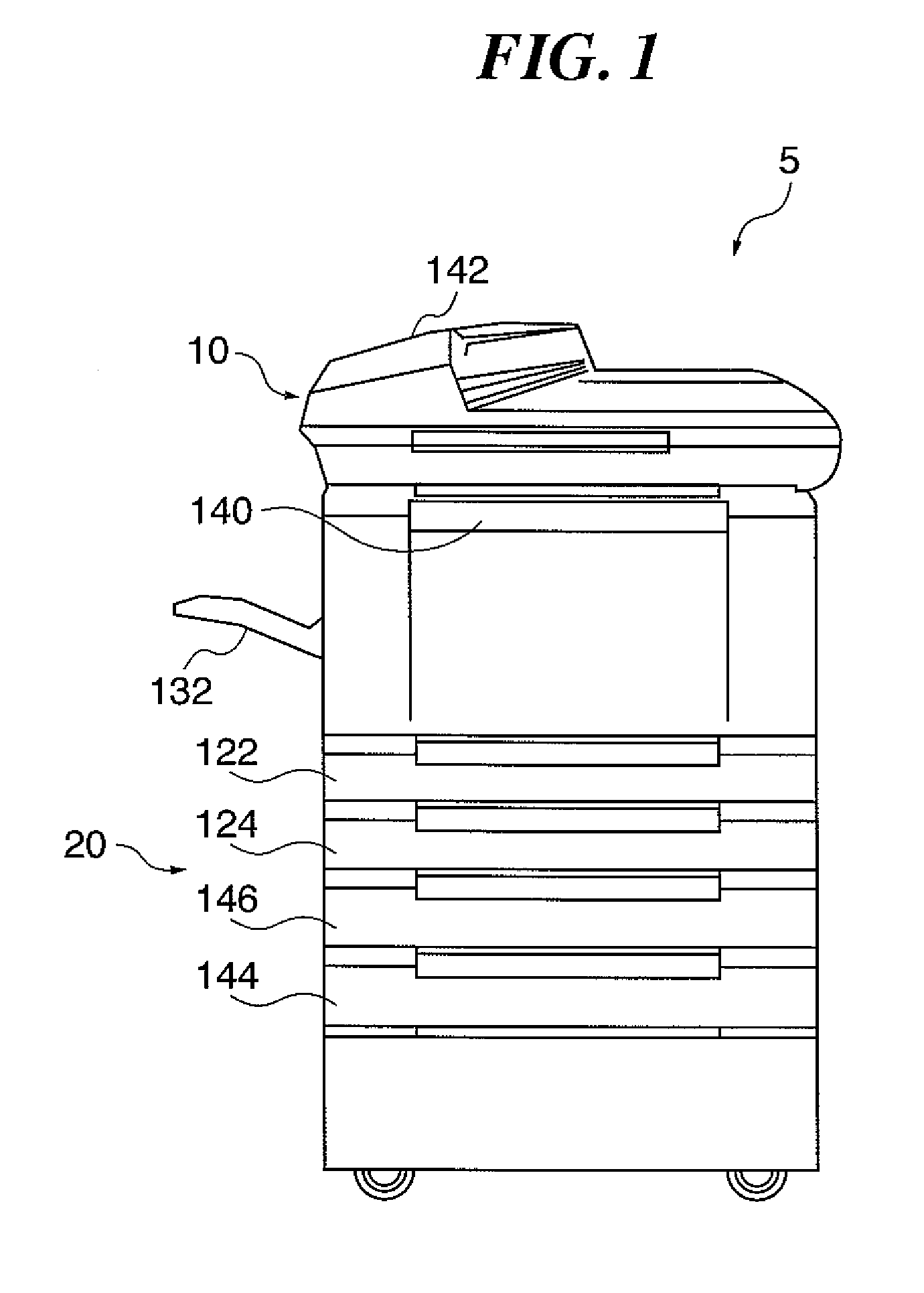
[0079]FIG. 1 is a view showing the appearance of a multifunction peripheral 5 according to the present invention. The multifunction peripheral 5 is comprised of a scanner section 10 which is an image input device, and a printer section 20 which is an image output device. The scanner section 10 illuminates an image on an original with a lamp, reads reflected light from the original with a CCD line sensor (hereinafter merely referred to as “the CCD”), and converts the reflected light into an electric signal, thereby processing the image on the original as image data. In reading originals, when a user places original sheets on an original feeder 142 and gives an instruction for starting reading, the original feeder 142 feeds the original sheets one by one.
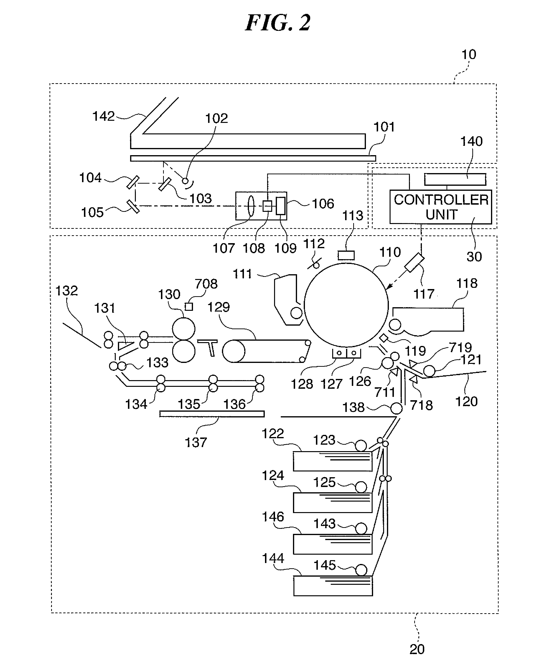
[0080] The printer section 20 is intended to convert image data into an image on a recording sheet, and in the present embodiment, performs printing by an electrophotographic process using a photosensitive drum or photosensitive belt....
second embodiment
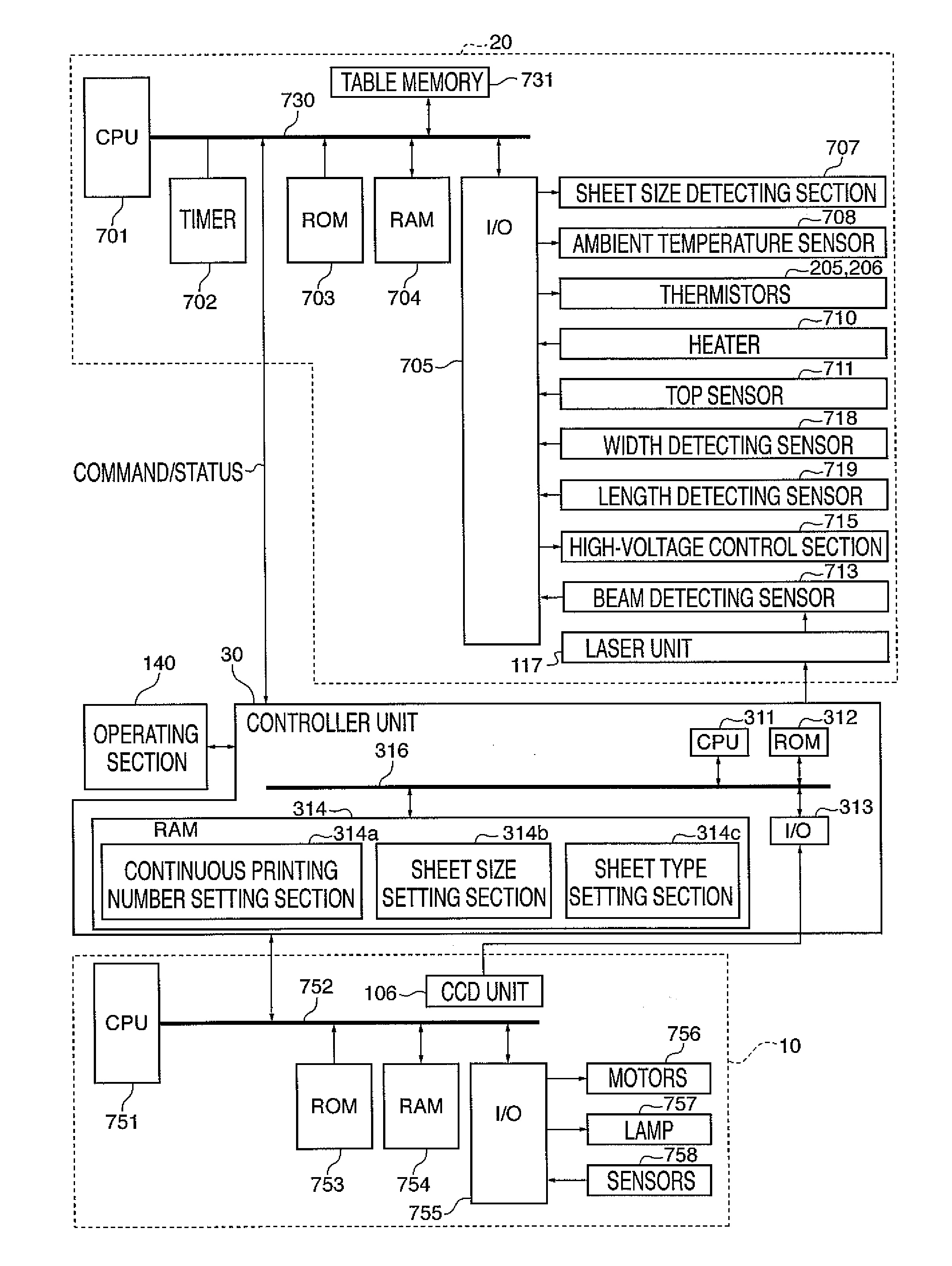
[0113] A description will now be given of how a recording sheet is conveyed in the multifunction peripheral 5 constructed as described above. FIG. 21 is a flowchart showing the procedure of a throughput timer determining process in conveying a recording sheet. A processing program for implementing the process is stored in the ROM 7 within the engine controller and executed by the CPU 701. The number of prints to be continuously produced and the sheet size set through the operation of the operating unit 140 by an operator are stored in advance in the number-of-continuous print setting section 314a and the sheet size setting section 314b, respectively, within the ROM 314 of the main controller 30.
[0114] First, as in the steps S1 and S2 of the first embodiment described above, a command indicative of the continuous printing number and a command indicative of the recording sheet size are received from the controller unit (main controller) 30 (steps S21 and S22). Further, a command indi...
third embodiment
[0118]FIG. 22 is a view showing how the size of a recording sheet being conveyed is detected according to the In a direction orthogonal to the direction in which recording sheets are conveyed, the width detecting sensor 718 (FIG. 1) that detects the width of a recording sheet is disposed at a distance of a width W from a reference point A. On a conveying path through which recording sheets pass, the length detecting sensor 719 (FIG. 1) that detects the length of a recording sheet is disposed.
[0119] Although depending on the width of recording sheets, there may be cases where the width detecting sensor 718 does not detect recording sheets, the length detecting sensor 719 is disposed at such a location as to detect all the recording sheets. When the width detecting sensor 718 detects a recording sheet being conveyed, this means that the recording sheet has a width not less than the width W. Also, the length of a recording sheet being conveyed is detected by measuring the time elapsed...
PUM
 Abstract
Description
Claims
Application Information