Printing head, printing device and printing method for rapid forming of metal piece

A printing device and printing head technology, applied in the direction of additive processing, etc., can solve the problems of low printing efficiency, achieve the effects of improving printing efficiency, improving utilization rate, and overcoming low printing efficiency

Inactive Publication Date: 2015-12-02
SHANGHAI SHENGKUANG ELECTROMECHANICAL TECH
View PDF11 Cites 15 Cited by
  • Summary
  • Abstract
  • Description
  • Claims
  • Application Information

AI Technical Summary

Problems solved by technology

[0023] The purpose of the present invention is to propose a printing head, a printing device and a printing method for rapid prototyping of metal parts, to overcome the shortcomings of the low printing efficiency of metal part 3D printers in the prior art, and to realize rapid and high-precision printing of three-dimensional metal parts

Method used


Image

  • Printing head, printing device and printing method for rapid forming of metal piece
  • Printing head, printing device and printing method for rapid forming of metal piece
  • Printing head, printing device and printing method for rapid forming of metal piece

Examples


Embodiment 1

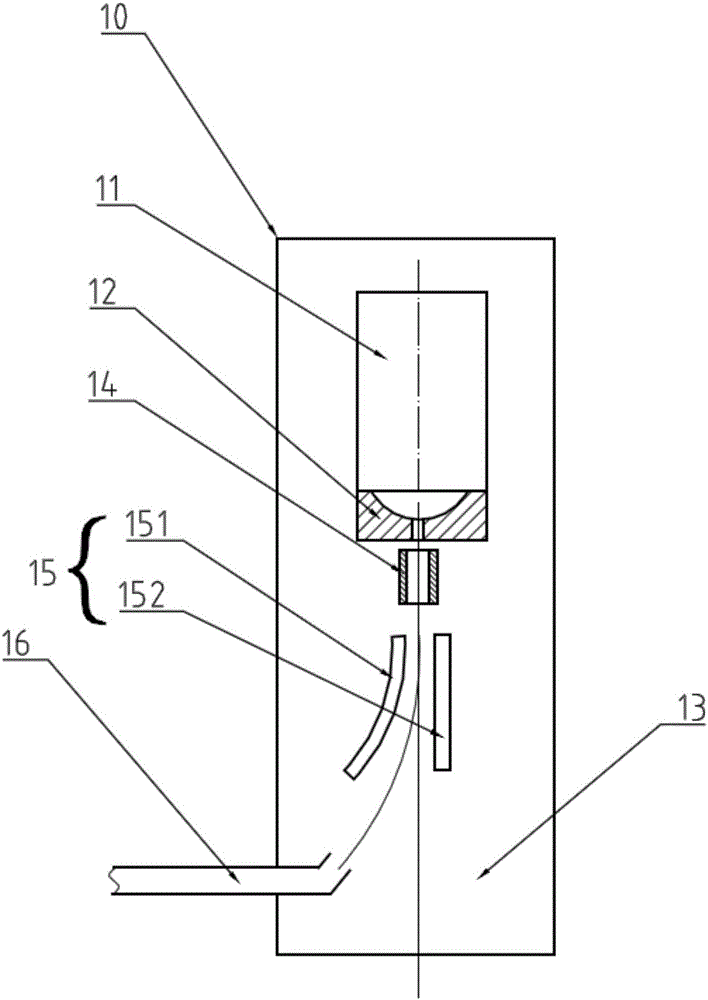
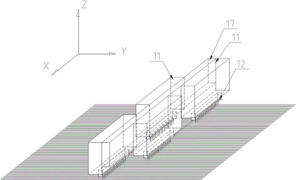
[0073] This embodiment discloses a printing head 10 for rapid prototyping of metal parts, which includes a body 11 and multi-nozzles 12 , and the multi-nozzles 12 are arranged on the body 11 .

[0074] Such as figure 1 As shown, the print head 10 of the present embodiment also includes: a mounting base plate 13, a first electrode 14 for controlling the electrical properties of the electroplating solution ejected through the multi-nozzle 12, and a non-neutral electroplating solution for making the electrical properties The deflected second common electrode 15 and the recovery tank 16 for receiving the deflected electroplating solution for recovery.

[0075] The main body 11, the multi-nozzle 12, the first electrode 14, the second common electrode 15 and the recovery tank 16 of this embodiment are as figure 1 As shown, they are sequentially arranged on the same side of the installation base plate 13 from top to bottom, the recovery tank 16 is arranged on the lower side of the s...

Embodiment 2

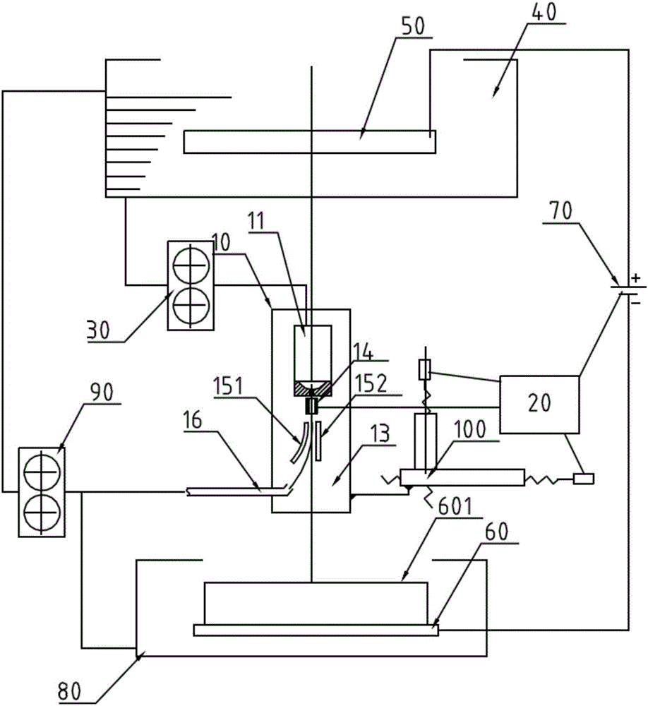
[0086] Such as figure 2 As shown, this embodiment proposes a printing device for rapid prototyping of metal parts, including a control system 20, a booster pump 30, a print head 10, an electroplating solution tank 40, a first electroplating plate 50, and a second electroplating plate 60 And electroplating power supply 70, one end of electroplating power supply 70 is connected with the first electroplating pole plate 50, and the other end of electroplating power supply 70 is connected with the second electroplating pole plate 60, and the first electroplating pole plate 50 is placed in the electroplating solution box 40, the second One side of the electroplating pole plate 60 faces the print head 10, and the electroplating solution in the electroplating solution tank 40 is pumped to the print head 10 by the booster pump 30, and the electroplating solution is ejected to the second electroplating pole plate 60 by the print head 10. Electrochemical deposition or electrolytic etchi...

Embodiment 3

[0112] This embodiment proposes a rapid prototyping printing method for metal parts, which uses electroplating solution to form electrochemical deposition or electrolytic etching layer by layer to print metal parts. During the electrochemical deposition or electrolytic etching process of the electroplating solution, Controlling the electrical properties of the plating solution.

[0113] At the position where the electroplating solution needs to be printed, the electroplating solution is directly sprayed onto the position to complete the printing of the position.

[0114] At positions that do not need to be printed, the electrical characteristics of the ejected electroplating solution are changed so that the electroplating solution is deflected so that the electroplating solution does not appear at the position that does not need to be printed.

[0115] Specifically, in this embodiment, the printing device described in Embodiment 2 prints metal parts (the specific structure and...


PUM


Abstract

The invention discloses a printing head, a printing device and a printing method for rapid forming of a metal piece. The printing head comprises a body, a plurality of nozzles, a first electrode and a second common electrode. When the printing head is in the working state, electroplate liquid is sprayed out through the multiple nozzles and sequentially passes through the first electrode and the second common electrode. The printing device is provided with the printing head. According to the printing method, when electrochemical deposition or electrolytic etching is conducted on the electroplate liquid, the electroplate liquid is electrified and is directly sprayed onto a position needing to be printed; in the position which does not need to be printed, the electroplate liquid deflects when flowing through a deflection electric field by changing the electrical characteristic of the electroplate liquid, and the electroplate liquid is prevented from being sprayed onto the position which does not need to be printed. By the adoption of the printing head, the printing device and the printing method for rapid forming of the metal piece, the defects that a three-dimensional (3D) printer for the metal piece in the prior art is low in printing efficiency and low in precision are overcome, and rapid, high-quality and high-precision printing of 3D metal pieces is achieved.

Description

technical field [0001] The invention relates to the technical field of rapid prototyping, in particular to a printing head for rapid prototyping of metal parts, a printing device and a printing method. Background technique [0002] Rapid prototyping technology can directly accept product design (CAD) data without preparing any molds, cutting tools and fixtures, and quickly manufacture samples, molds or models of new products. Its basic principle is "manufacturing layer by layer, superimposing layer by layer", which is similar to the integral process in mathematics. [0003] With the rapid development of rapid prototyping technology, 3D printing is mainly realized in the following ways: [0004] 1. SLA body photolithography modeling technology [0005] Technical principle: use specific wavelength and intensity of laser light to focus on the surface of photo-curable material, so that it can be solidified in sequence from point to line and from line to surface. The lift tabl...

Claims


Application Information

Patent Timeline
Patent Type & Authority Applications(China)
IPC IPC(8): C25D5/08B33Y30/00
Inventor 程诗虎
Owner SHANGHAI SHENGKUANG ELECTROMECHANICAL TECH
Why Eureka
Try Eureka