
Clamping device used for bottle caps

A clamping device and bottle cap technology, which is applied in the direction of chucks, manipulators, manufacturing tools, etc., can solve the problems that affect the capping efficiency and the difficulty of cap grasping, and achieve the effect of high capping efficiency and stable clamping

Pending Publication Date: 2020-09-08
JIANGSU NEWAMSTAR PACKAGING MACHINERY
View PDF0 Cites 2 Cited by
  • Summary
  • Abstract
  • Description
  • Claims
  • Application Information

AI Technical Summary

Problems solved by technology

It makes it difficult to grab the cap and seriously affects the capping efficiency

Method used


Image

  • Clamping device used for bottle caps
  • Clamping device used for bottle caps
  • Clamping device used for bottle caps

Examples


Embodiment Construction

[0027] The technical solution of the present invention will be further described below in conjunction with the accompanying drawings.

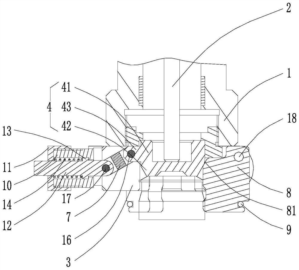
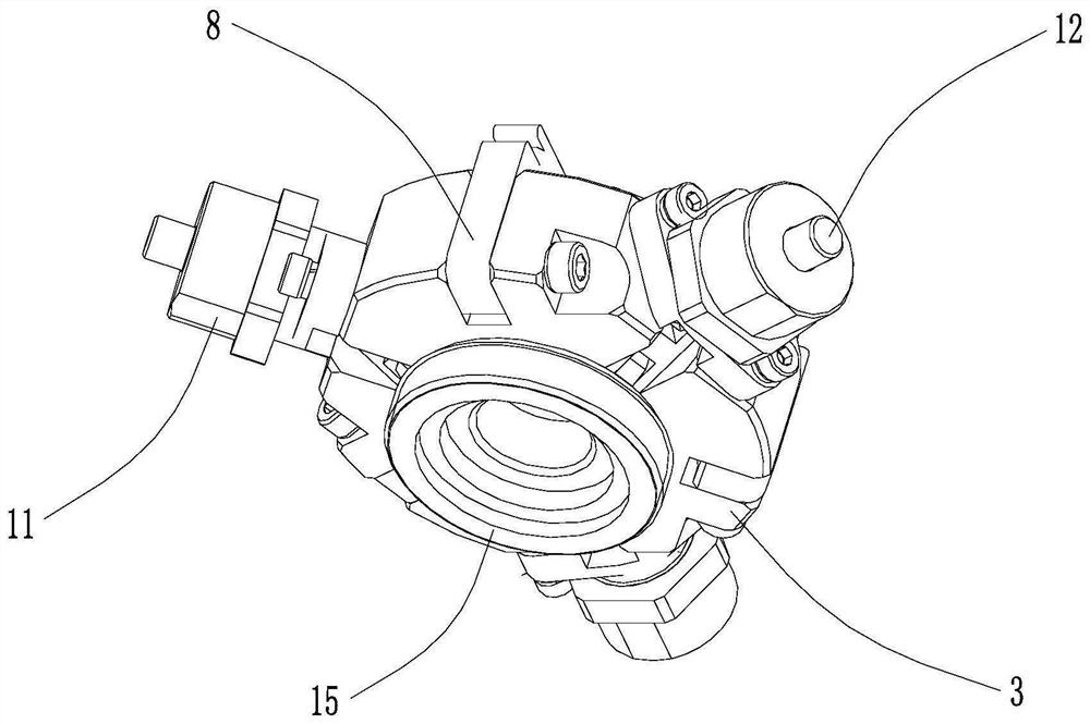
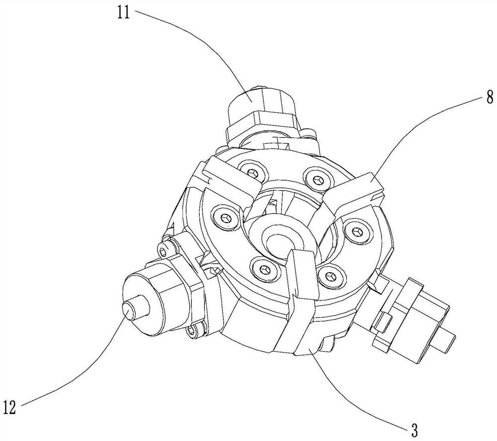
[0028] see Figure 1-4 As shown, the above-mentioned clamping device for bottle caps is connected to the lower end of the capping base 1, and the capping base 1 is provided with a push rod 2 that can move up and down. The device includes a mounting base 3 with a cylindrical inner cavity, and a mounting ring 15 provided on the top of the mounting base 3 for matching with the cover base 1 for installation. The ejector rod 2 and the mounting ring 15 extend coaxially with the cylindrical cavity, and the ejector rod 2 can pass through the mounting ring 15 and enter the cylindrical cavity. Specifically, the outer peripheral portion of the mounting ring 15 is provided with external threads, which can be screwed inwardly into the cover seat 1 .

[0029] see figure 1 As shown, the above-mentioned clamping device for bottle caps also includes a slidi...


PUM


Abstract

The invention discloses a clamping device used for bottle caps. The clamping device comprises a mounting seat with a columnar inner cavity, a sliding seat slidably arranged in the columnar inner cavity in a penetrating manner, first grooves, second grooves and an elastic abutting mechanism arranged on the mounting seat, wherein the first grooves and the second grooves are arranged in the mountingseat and communicate with the columnar inner cavity. The elastic abutting mechanism comprises a connecting rod arranged in the first grooves, wherein one end of the connecting rod is rotationally connected to the sliding seat. The elastic abutting mechanism is used for applying radial elastic abutting force to the sliding seat through the connecting rod. The device further comprises at least two clamping jaws and elastic hoops, wherein the clamping jaws are rotationally arranged in the second grooves and used for rotating in and out of the columnar inner cavity, and the elastic hoops are arranged on the outer sides of the clamping jaws in a hooped manner. The clamping jaws are used for being connected with the sliding seat in an abutting manner through the inner sides of the clamping jaws.When the sliding seat is driven by an ejector rod to move downwards and enter the clamping jaws, the sliding seat drives the clamping jaws to open. When the sliding seat is driven by bottle caps to move upwards and retreat from the clamping jaws, the clamping jaws are driven by the elastic hoops to be tightened. The clamping device is suitable for clamping of bottle caps in different shapes, andclamping is rapid and stable.

Description

technical field [0001] The invention relates to the technical field of capping, in particular to a clamping device for bottle caps. Background technique [0002] In the capping process, caps with various irregular shapes are often encountered, such as top slopes, spherical surfaces, patterns, etc. It makes it difficult to grab the cap, which seriously affects the capping efficiency. Contents of the invention [0003] The object of the present invention is to provide a clamping device for bottle caps, which is suitable for clamping and capping caps of different shapes, fast and stable clamping, and high capping efficiency. [0004] In order to achieve the above object, the technical scheme adopted in the present invention is: [0005] A clamping device for bottle caps, which is connected to the lower end of the capping seat, the capping seat is provided with a push rod, and the device includes a mounting seat with a cylindrical inner cavity, which can slide up and down an...

Claims


Application Information

Patent Timeline
Patent Type & Authority Applications(China)
IPC IPC(8): B25J15/00B25J15/08
CPCB25J15/0038B25J15/08
Inventor 沈军赵斌钱飞虎
Owner JIANGSU NEWAMSTAR PACKAGING MACHINERY
Learn More