
Relay shell mounting production line

A production line and relay technology, applied in relays, relay bases/shells/covers, circuits, etc., can solve the problem of low installation efficiency of relay shells, and achieve the effect of high degree of automation, simple structure and labor saving.

Inactive Publication Date: 2020-09-08
HUANGSHAN WANGRONG ELECTRONICS
View PDF4 Cites 0 Cited by
  • Summary
  • Abstract
  • Description
  • Claims
  • Application Information

AI Technical Summary

Problems solved by technology

[0004] The purpose of the present invention is to solve the problem of low installation efficiency of relay casings in the prior art, and propose a production line for installing relay casings

Method used


Image

  • Relay shell mounting production line
  • Relay shell mounting production line

Examples


Embodiment 1

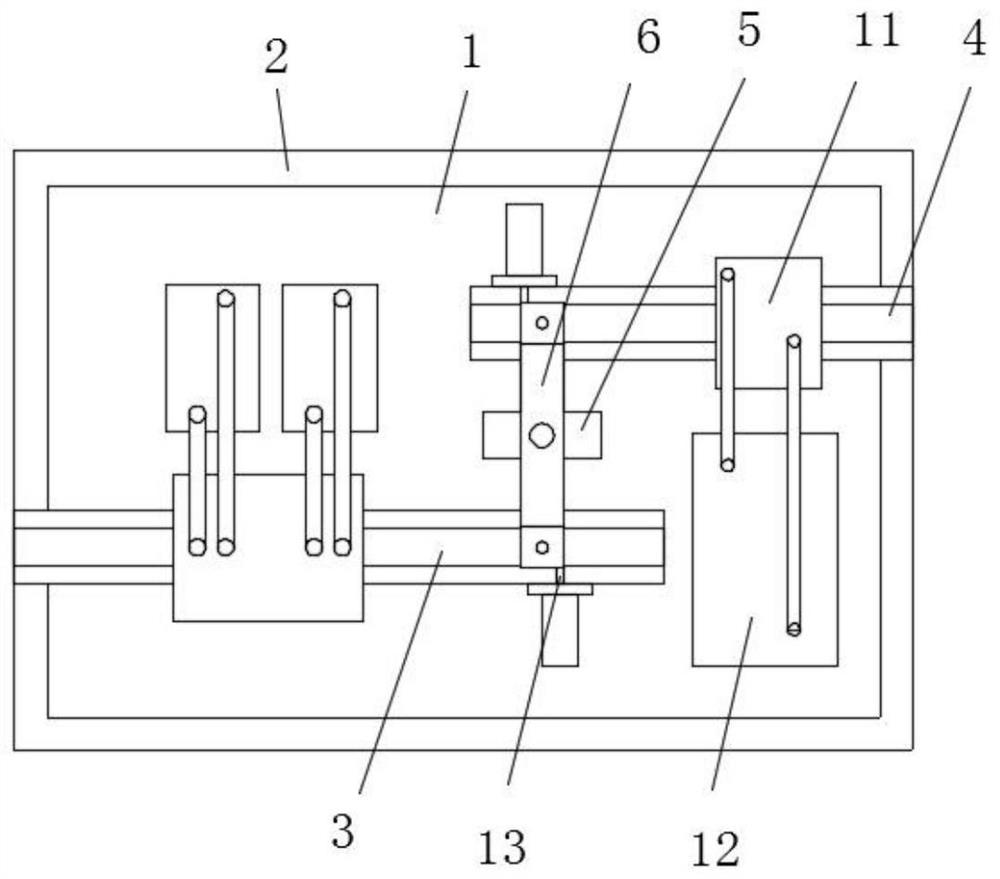
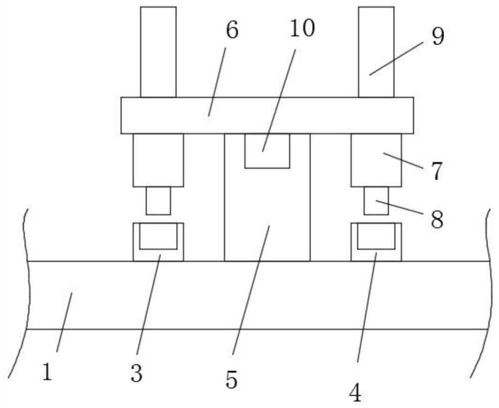
[0020] refer to Figure 1-2 , a relay shell installation production line, including a workbench 1 and an outer cover 2 fixed on the top of the workbench 1, two ends of the top of the workbench 1 are provided with a mounting frame conveyor belt 3 and a shell conveyor belt 4 arranged in parallel to each other, and the mounting frame conveyor belt 3 There is a support column 5 fixed on the top of the workbench 1 between the shell conveyor belt 4, and the top of the support column 5 is rotatably connected with a horizontal plate 6, and the bottoms of both ends of the horizontal plate 6 are equipped with a movable plate 7 slidingly connected with it. The bottom of each movable plate 7 is respectively fixed with mechanical claw one 8 and mechanical claw two. 9. The output end of the hydraulic cylinder 9 passes through the horizontal plate 6 and is fixed on the top of the movable plate 7. The electric turntable 10 is embedded in the top of the support column 5, and the horizontal pla...

Embodiment 2

[0024] refer to Figure 1-2 , a relay casing installation production line, the same as the first embodiment, the difference between this embodiment and the first embodiment is that a blowing mechanism 1 is provided directly above the casing conveyor belt 4, and the blowing mechanism 1 is included directly above the casing conveyor belt 4 The end cover 11 moving up and down, the filter box 12 located on one side of the shell conveyor belt 4, the air inlet pipe and the air outlet pipe connecting the end cover 11 and the filter box 12, and the negative pressure fan and filter screen located in the filter box 12, the end cover 11 It is an E-shaped structure, the bottom of the end cover 11 is tightly pressed on the top of the housing conveyor belt 4, the installation frame conveyor belt 3 is provided with an air blowing mechanism 2 having the same structure as the blowing mechanism 1, and the bottom of the filter box 12 is provided for the mounting frame conveyor belt 3 to pass thro...


PUM


Abstract

The invention belongs to the field of relay processing devices, and discloses a relay shell mounting production line which is used for solving the problem of low mounting efficiency of an existing relay shell. The relay shell mounting production line comprises a workbench and an outer cover fixed to the top of the workbench, wherein a mounting frame conveying belt and a shell conveying belt whichare arranged in parallel are arranged at the two ends of the top of the workbench, a supporting column fixed to the top of the workbench is arranged between the mounting frame conveying belt and the shell conveying belt, a transverse plate is rotatably connected to the top of the supporting column, movable plates slidably connected with the transverse plate are installed at the bottom of the two ends of the transverse plate correspondingly, a first mechanical claw and a second mechanical claw are fixed to the bottom of the two movable plates correspondingly, and the first mechanical claw and the second mechanical claw are located right above the installing frame conveying belt and right above the shell conveying belt respectively. The relay shell mounting production line is simple in structure, compact in design, small in occupied space, high in automation degree, capable of saving labor and efficient in relay shell assembling.

Description

technical field [0001] The invention relates to the technical field of relay processing devices, in particular to a relay shell installation production line. Background technique [0002] When installing the relay casing, the usual way is to set the casing conveyor belt, the mounting frame conveyor belt and the finished product conveyor belt in parallel, and the staff will assemble the casing on the casing conveyor belt and the mounting frame on the mounting frame conveyor belt and place them on the finished product conveyor belt. This kind of processing method has low processing efficiency. The existing shell installation production line has complex structure, high price and large space occupation. [0003] Therefore, it is necessary for us to design an automatic relay housing installation production line with a simple structure to solve the above problems. Contents of the invention [0004] The object of the present invention is to solve the problem of low installation...

Claims


Application Information

Patent Timeline
Patent Type & Authority Applications(China)
IPC IPC(8): H01H49/00H01H45/02B65G47/90B01D46/00
CPCH01H49/00H01H45/02B65G47/90B01D46/00
Inventor 胡志敏余胜飞危奎
Owner HUANGSHAN WANGRONG ELECTRONICS
Learn More