
Oral cavity distrction examination device for department of pediatrics

An inspection device and oral cavity technology, which is applied in oral mirrors, applications, medical science, etc., can solve problems such as the inability to change the size of the oral cavity, and achieve the effect of convenient pressing and clear observation

Pending Publication Date: 2020-09-11
吴青保
View PDF7 Cites 3 Cited by
  • Summary
  • Abstract
  • Description
  • Claims
  • Application Information

AI Technical Summary

Problems solved by technology

[0005] In order to overcome the disadvantage that the current oral distraction device cannot change the size of the oral distraction, the technical problem to be solved is: provide a pediatric oral distraction inspection device that can change the size of the oral distraction of children and is convenient for observation

Method used


Image

  • Oral cavity distrction examination device for department of pediatrics
  • Oral cavity distrction examination device for department of pediatrics
  • Oral cavity distrction examination device for department of pediatrics

Examples


Embodiment 1

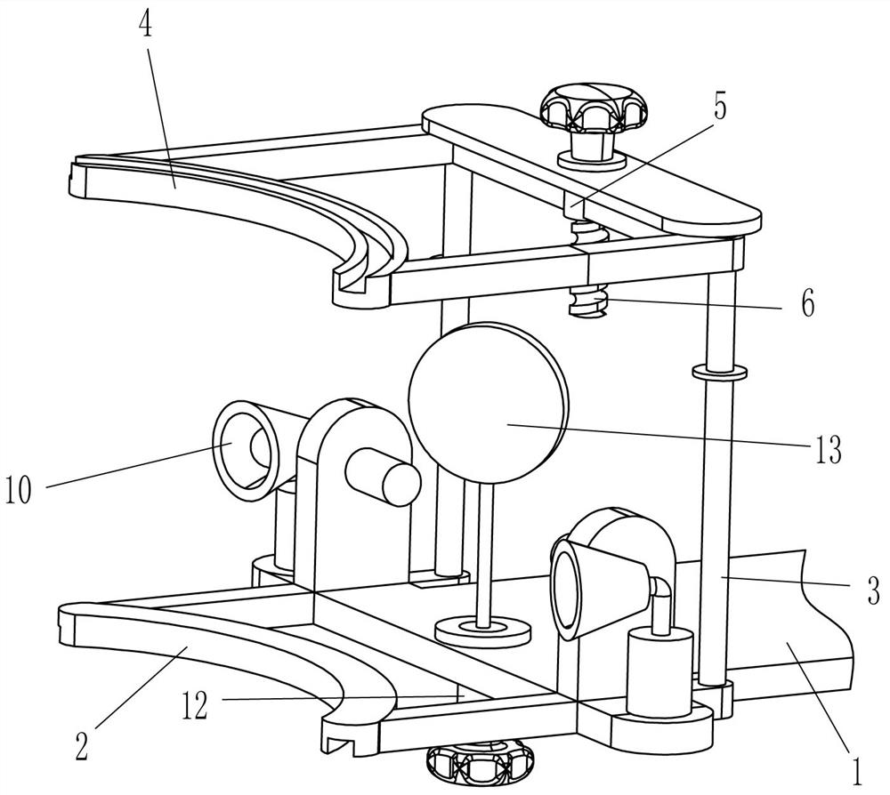
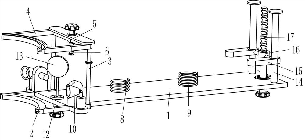
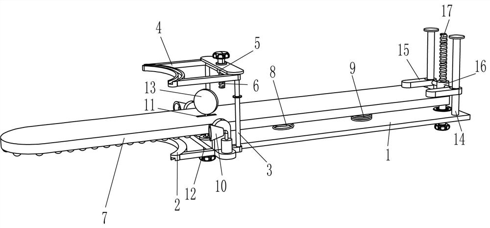
[0018] A pediatric oral distraction inspection device, such as Figure 1-3 As shown, it includes a mounting plate 1, a stretching assembly and a tongue depressing assembly. The left side of the mounting plate 1 is installed with a stretching assembly for opening the oral cavity through rotation. Tongue assembly.

[0019] Such as Figure 1-3 As shown, the expansion assembly includes a lower bite plate 2, a concave rod 3, an upper bite plate 4, a first nut 5 and a first bolt 6, the lower bite plate 2 is welded on the left side of the installation plate 1, and the left side of the installation plate 1 A concave rod 3 is welded between the front and rear sides. The upper part of the concave rod 3 slides and is provided with an upper bite plate 4. The right part of the upper bite plate 4 is equipped with a first nut 5. The top of the concave rod 3 is rotated in the middle and is provided with a second A bolt 6, the first bolt 6 is connected with the first nut 5 through threads. ...

Embodiment 2

[0025] On the basis of Example 1, such as Figure 1-3 As shown, an illuminating lamp 10 is also included, and the illuminating lamp 10 is installed on both sides of the left side of the mounting plate 1, front and back.

[0026] Such as Figure 1-3 Shown, also comprise rotating rod 12 and convex lens 13, tongue depressor 7 left parts have a word hole 11, the mounting plate 1 below the word hole 11 is provided with rotating rod 12 in a rotating manner, and rotating rod 12 passes through the word hole 11. A convex lens 13 is connected to the hole 11 and the top end of the rotating rod 12 .

[0027] Such as Figure 1-2 As shown, guide rod 14, slide plate 15, second nut 16 and second bolt 17 are also included. Guide rod 14 is provided on both sides, front and rear, right side, top side of mounting plate 1, and slide plate is provided with sliding type between guide rod 14 bottoms. 15. A second nut 16 is provided in the middle of the slide plate 15, and a second bolt 17 is threa...


PUM


Abstract

The invention relates to an examination device, in particular to an oral cavity distraction examination device for the department of pediatrics. The technical problem to be solved is to provide the oral cavity distraction examination device for the department of pediatrics, which can change the distraction size of an oral cavity of a child and is convenient to observe. An oral cavity distraction examination device for the department of pediatrics comprises a mounting plate; a distraction assembly which is mounted on the mounting plate and distracts the oral cavity in a rotating manner; and a tongue pressing assembly which is mounted on the mounting plate and performs tongue pressing in a rotating manner. By changing the position of an upper bite plate, the distraction size of the oral cavity can be changed, observation of a doctor is facilitated; the tongue of the child can be conveniently and rapidly pressed through the tongue pressing assembly, and a user can conveniently use the device; the observation is conducted through amplification of a convex lens, and observation is conducted by changing the angle of the convex lens through a rotating rod, so that the observation of the doctor is clearer; and the tongue of the child is pressed by screwing a second bolt, so that the tongue of the child can be pressed more conveniently.

Description

technical field [0001] The invention relates to an examination device, in particular to a pediatric mouth distraction examination device. Background technique [0002] The oral cavity refers to the cavity in the mouth, which is the beginning part of the digestive tract and consists of the lips, cheeks, hard palate, and soft palate. The oral cavity contains teeth, tongue, salivary glands and other organs. The front wall of the oral cavity is the lips, the side wall is the cheeks, the roof is the palate, and the floor of the mouth is the mucosa and muscles. The oral cavity is divided into the anterolateral oral vestibule and the posteromedial oral cavity by the upper and lower dental arches; when the upper and lower teeth occlude, the oral vestibule and the oral cavity proper can be communicated through the gap behind the third molars. Clinically, when the patient's teeth are tightly closed, the mouth gag or cannula can be placed through this channel to inject drugs or nutri...

Claims


Application Information

Patent Timeline
Patent Type & Authority Applications(China)
IPC IPC(8): A61B1/24A61B1/247A61B1/06
CPCA61B1/24A61B1/247A61B1/06
Inventor 吴青保
Owner 吴青保
Learn More