Automatic pulse dust removal cleaning system and method based on pressure detection

An automatic pulse and pressure technology, applied in the field of sanitation vehicles, can solve problems such as variation, time-consuming and laborious, and inability to automatically feed back filter cartridges

Inactive Publication Date: 2020-09-11
XUZHOU XUGONG ENVIRONMENTAL TECH CO LTD
View PDF9 Cites 1 Cited by
  • Summary
  • Abstract
  • Description
  • Claims
  • Application Information

AI Technical Summary

Problems solved by technology

The inventor found that the existing pulse dust removal has the following disadvantages: 1. The user cannot determine whether the poor effect of picking up garbage is caused by the clogging of the filter cartridge;
(According to existing experience, it is easiest to unclog the filter cartridge in the early stage of clogging trend) 3. The ability to clear the clogging cannot be automatically adjusted according to the clogging situation of the filter cartridge, which often leads to complete clogging of the filter cartridge, and the filter cartridge needs to be disassembled and cleaned manually. Time-consuming and labor-intensive, very troublesome

Method used


Image

  • Automatic pulse dust removal cleaning system and method based on pressure detection
  • Automatic pulse dust removal cleaning system and method based on pressure detection

Examples


Embodiment 1

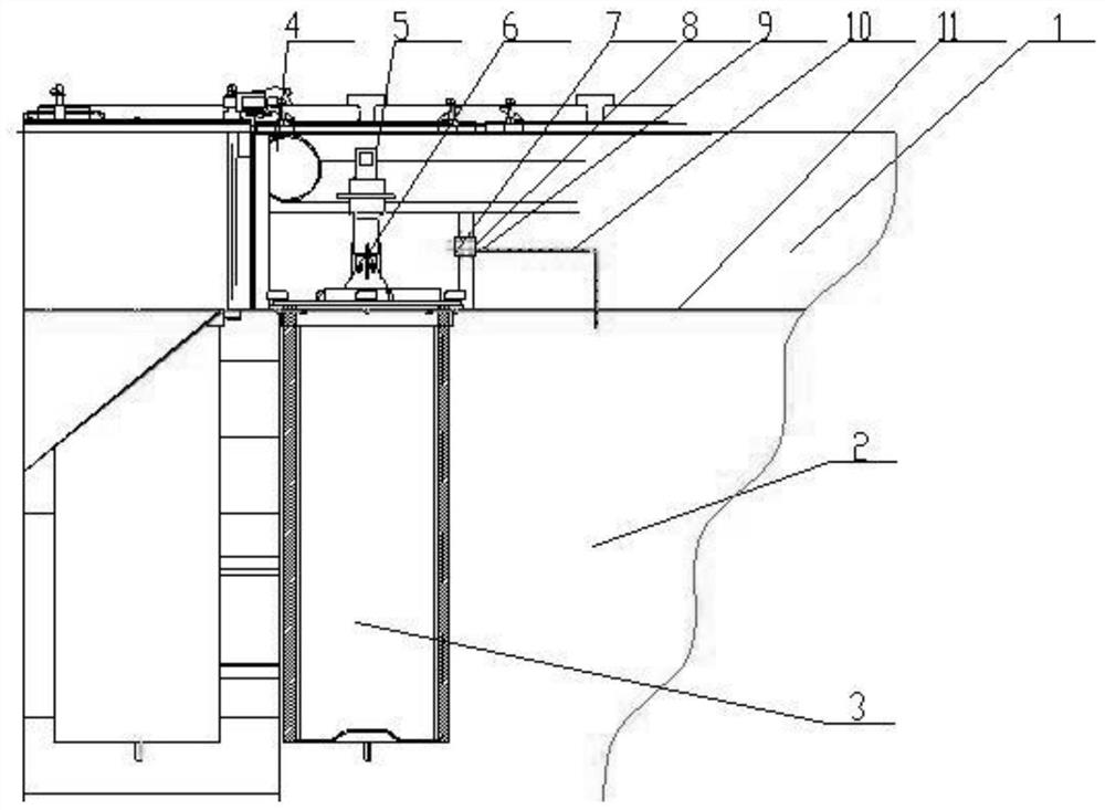
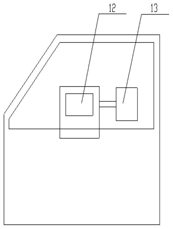
[0029] The invention provides an automatic pulse dust removal and cleaning system based on pressure detection, such as figure 1 As shown, it includes a purified air chamber 1, a filtered air chamber 2, a filter cartridge 3, an air bag 4, a pulse valve 5, an air injection hole 6, a differential pressure gauge 7, a first measuring port 8, a second measuring port 9, an air pipe 10, Partition 11 , cab controller 12 and monitor 13 . The purified gas chamber 1 and the filtered gas chamber 2 are of an integral box structure, and the purified gas chamber 1 and the filtered gas chamber 2 are separated by a partition 11 . The filter cartridge 3 is installed in the filter air chamber 2, and the filter air chamber 2 communicates with the dustbin.

[0030] The filter cartridge 3 includes an inner ring filter element and an outer ring filter layer. The top of the inner ring filter element extends into the purified air chamber 1. After the gas in the filtered air chamber 2 enters the filter...

Embodiment 2

[0036] The present invention provides an automatic pulse dust removal and cleaning method based on pressure detection. The device used in this method is the device in Embodiment 1, and the device part will not be described in detail in this embodiment. This method comprises the steps:

[0037] Step 1. Monitor the pressure difference between the inside of the filter cartridge and the outside of the filter cartridge through the differential pressure gauge 7 .

[0038] Step 2. When the differential pressure of the differential pressure gauge 7 reaches the preset minimum (i.e., the filter cartridge tends to be clogged), the cab controller 12 controls the pulse valve 5 to appropriately increase the injection time of the pulse valve and reduce the injection interval. The stored compressed air of the air bag 4 is blown to the inside of the filter cartridge through the air injection hole 6, and the blockage of the filter cartridge is quickly cleared. Once the blockage is removed, the ...


PUM


Abstract

The invention discloses an automatic pulse dust removal cleaning system and method based on pressure detection. The system comprises a purifying air chamber and a filtering air chamber, the filteringair chamber is communicated with a garbage can, a filter cylinder is installed in the filtering air chamber, an air pocket and a pulse valve are connected in the purifying air chamber, the air pocketis communicated with the pulse valve, the bottom end of the pulse valve penetrates through the purifying air chamber and extends into the filter cylinder, and an air spraying hole is formed in the bottom end of the pulse valve; a differential pressure gauge is connected in the purifying air chamber and comprises a first measuring port and a second measuring port, the first measuring port is used for detecting the pressure of the purifying air chamber, the second measuring port is communicated with the filtering air chamber through an air pipe, and the second measuring port is used for detecting the pressure of the filtering air chamber; and the differential pressure gauge and the pulse valve are in communication connection with a control display device. The pressure difference between theinner side and the outer side of the filter cylinder is detected through the differential pressure gauge to achieve that the blockage condition of the filter cartridge is detected, and the trouble that the filter cylinder needs to be manually disassembled for cleaning after being blocked is reduced.

Description

technical field [0001] The invention relates to the technical field of sanitation vehicles, in particular to an automatic pulse dust removal and cleaning system and method based on pressure detection. Background technique [0002] Existing dry road sweeper is equipped with the filter cartridge of filtering in order to solve the working dust that anhydrous causes. However, during the working process, dust is often adsorbed on the filter cartridge, causing the blockage of the pneumatic conveying of the road sweeper, which affects the working effect. The solution is to increase a reverse air flow to blow the dust on the surface of the filter cartridge. [0003] The reverse air flow will reduce the suction effect, and it is impossible to reverse the blowing flow infinitely. The existing technology is to use the pulse dust removal technology. No matter what the effect is, the reverse blowing flow is performed at a fixed time interval. The inventor found that the existing pulse d...

Claims


Application Information

Patent Timeline
IPC IPC(8): B01D46/46B01D46/42B01D46/24
CPCB01D46/0086B01D46/2411B01D46/446B01D46/46B01D2279/40B01D46/72B01D46/71
Inventor 程磊单龙张安温玉霜朱邦龙刘天波孙永强
Owner XUZHOU XUGONG ENVIRONMENTAL TECH CO LTD
Why Eureka
Try Eureka