Dust removal spraying system for building safety engineering

A technology of spraying system and safety engineering, applied in the field of dust removal spraying system for building safety engineering, can solve problems such as water resource waste, and achieve the effect of increasing the spraying area

Inactive Publication Date: 2020-09-11
谢洁萍
View PDF6 Cites 5 Cited by
  • Summary
  • Abstract
  • Description
  • Claims
  • Application Information

AI Technical Summary

Problems solved by technology

[0004] The purpose of the present invention is to solve the problem that the existing sprinkler system for building safety engineering can only spray in one direction when it is in use, and the use of multiple sprinklers will cause waste of water resources. A dust removal and sprinkler system for building safety engineering

Method used


Image

  • Dust removal spraying system for building safety engineering
  • Dust removal spraying system for building safety engineering
  • Dust removal spraying system for building safety engineering

Examples


Embodiment 1

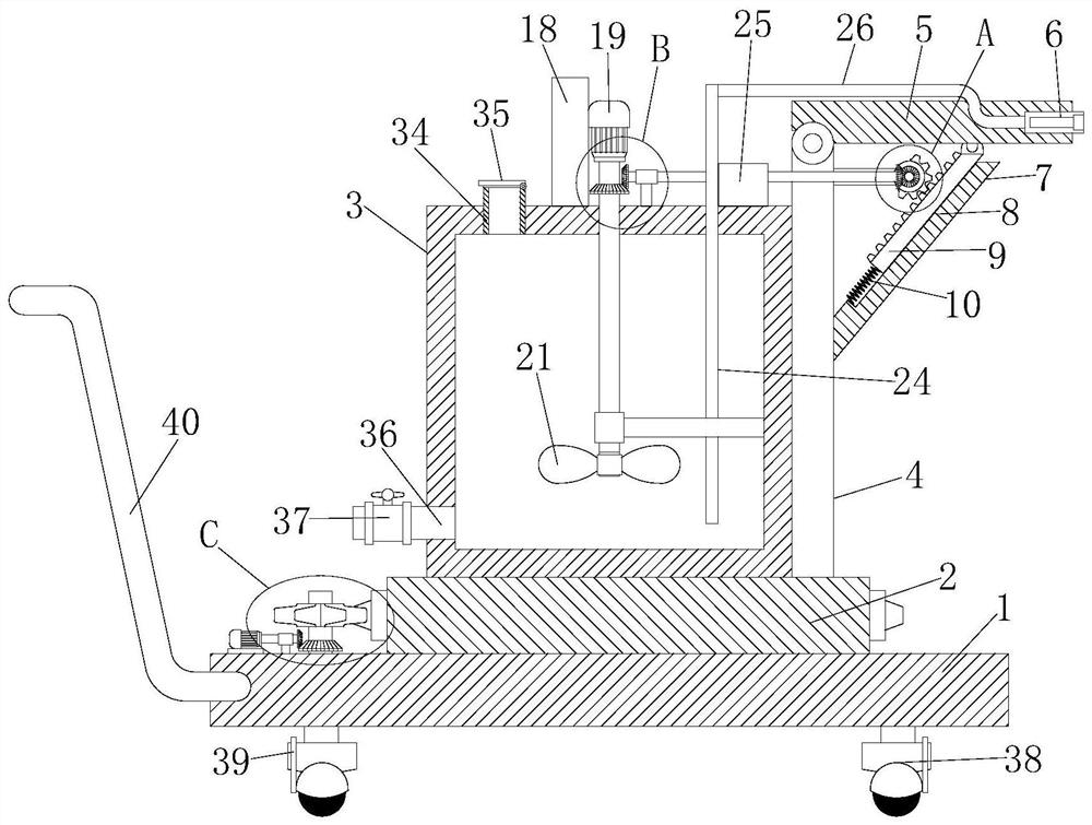
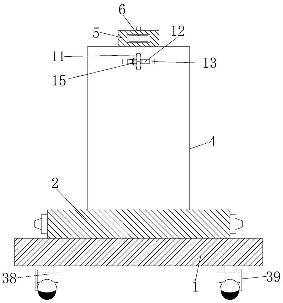
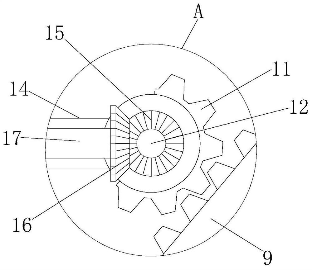
[0027] refer to Figure 1-5 , a dust removal and spraying system for building safety engineering, comprising a bottom plate 1, the top of the bottom plate 1 is rotatably connected to a turntable 2, the top of the turntable 2 is fixedly connected to a water tank 3 and a side plate 4, and the side plate 4 is fixedly connected to a part of the water tank 3 Side, the top of the side plate 4 is hingedly connected with a horizontal plate 5, one end of the horizontal plate 5 is fixedly provided with an atomizing nozzle 6, one side of the side plate 4 is fixedly connected with a slanting rod 7, and a chute 8 is provided on the slanting rod 7, A rack 9 is slidably connected in the chute 8, and one end of a spring 10 is fixedly connected to the bottom end of the rack 9, and the other end of the spring 10 is fixedly connected to the inner wall of the bottom of the chute 8, and a sector gear is engaged on the rack 9 11. The first roller 12 is fixed on the sector gear 11, and the two ends ...

Embodiment 2

[0038] refer to Figure 1-5, a dust removal and spraying system for building safety engineering, comprising a bottom plate 1, the top of the bottom plate 1 is rotatably connected with a turntable 2, the top of the turntable 2 is fixedly welded with a water tank 3 and a side plate 4, and the side plate 4 is fixedly welded to a part of the water tank 3 Side, the top of the side plate 4 is hingedly connected with a horizontal plate 5, one end of the horizontal plate 5 is fixedly provided with an atomizing nozzle 6, one side of the side plate 4 is fixedly welded with a slanting rod 7, and a chute 8 is opened on the slanting rod 7, The chute 8 is slidingly connected with a rack 9, the bottom end of the rack 9 is fixedly welded with one end of the spring 10, and the other end of the spring 10 is fixedly welded on the bottom inner wall of the chute 8, and the rack 9 is meshed with a sector gear 11. The first roller 12 is fixedly set on the sector gear 11, and the two ends of the firs...


PUM


Abstract

The invention belongs to the technical field of dust removal spraying of buildings and especially provides a dust removal spraying system for the building safety engineering. The invention is to solvethe problem that in an existing dust removal spraying system for building safety engineering, a spraying head can only conduct spraying in one direction; a plurality of spray heads are used, so thatthe waste of water resources is caused; the invention provides the following scheme: the dust removal spraying system comprises a bottom plate, wherein a rotary table is rotatably connected to the topof the bottom plate, a water tank and a side plate are fixedly connected to the top of the rotary table, the side plate is fixedly connected to one side of the water tank, a transverse plate is hinged to the top of the side plate, an atomizing nozzle is fixedly arranged at one end of the transverse plate, an inclined rod is fixedly connected to one side of the side plate, and a rack is slidably connected into the sliding groove. The first bevel gear and the first rolling shaft can be rotated through the second bevel gear, then the fan-shaped gear is rotated, the rack and the transverse platecan be pushed to rotate upwards, and when the fan-shaped gear and the rack are staggered, the transverse plate can reset, so that the spraying area can be increased through reciprocating rotation.

Description

technical field [0001] The invention belongs to the technical field of dedusting and spraying for buildings, and in particular relates to a dedusting and spraying system for building safety engineering. Background technique [0002] Building construction refers to the production activities in the implementation stage of engineering construction. It is the construction process of various buildings. It can also be said to be the process of turning various lines on the design drawings into physical objects at designated locations. It includes basic engineering construction. , main structure construction, roofing engineering construction, decoration engineering construction, etc., the construction site is called "building construction site" or "construction site", also called construction site. With the improvement of environmental protection requirements, it is necessary to The dust on the construction site is purified to prevent the dust on the construction site from affecting...

Claims


Application Information

Patent Timeline
Patent Type & Authority Applications(China)
IPC IPC(8): B01D47/06
CPCB01D47/06
Inventor 谢洁萍
Owner 谢洁萍
Why Eureka
Try Eureka