
Metal plate separating stacking tray structure

A disc structure and sheet metal technology, applied in the field of sheet metal bending

Inactive Publication Date: 2020-09-11
重庆浪尖智能科技研究院有限公司
View PDF0 Cites 0 Cited by
  • Summary
  • Abstract
  • Description
  • Claims
  • Application Information

AI Technical Summary

Problems solved by technology

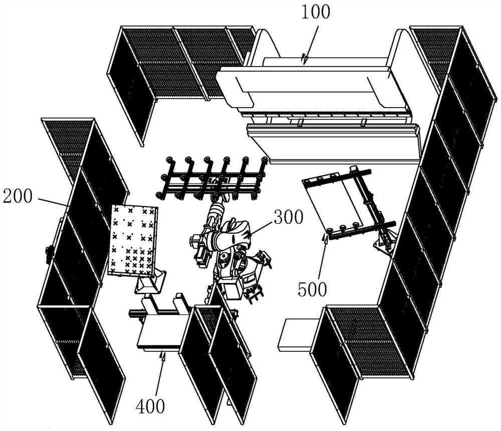
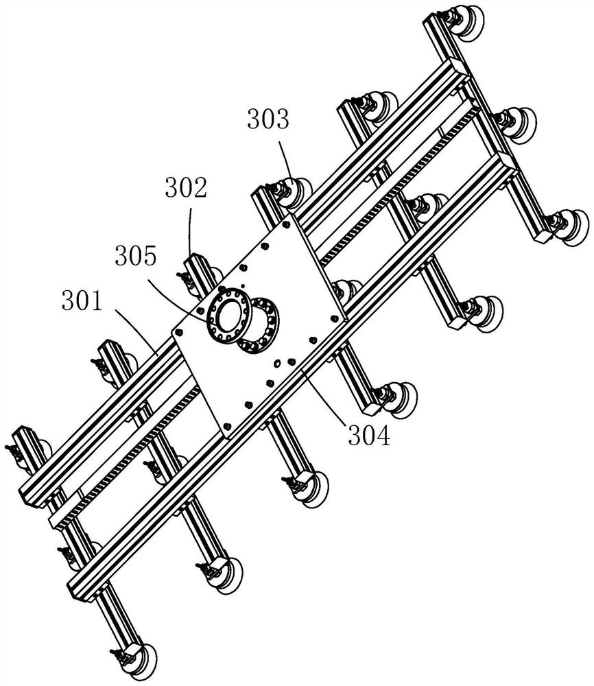
[0005] The purpose of the present invention is to provide a sheet metal sheet stamping structure, aiming to solve the problem in the prior art that the mechanical arm grabs multiple sheet materials at one time

Method used


Image

  • Metal plate separating stacking tray structure
  • Metal plate separating stacking tray structure
  • Metal plate separating stacking tray structure

Examples


Embodiment Construction

[0023] In order to make the object, technical solution and advantages of the present invention clearer, the present invention will be further described in detail below in conjunction with the accompanying drawings and embodiments. It should be understood that the specific embodiments described here are only used to explain the present invention, not to limit the present invention.

[0024] The implementation of the present invention will be described in detail below in conjunction with specific embodiments.

[0025] In the drawings of this embodiment, the same or similar symbols correspond to the same or similar components; The indicated orientation or positional relationship is based on the orientation or positional relationship shown in the drawings, and is only for the convenience of describing the present invention and simplifying the description, rather than indicating or implying that the referred device or element must have a specific orientation, or in a specific orien...


PUM


Abstract

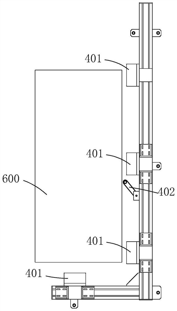
The invention relates to the technical field of metal plate bending, and discloses a metal plate separating stacking tray structure which comprises a stacking tray for placing metal plates and a mechanical arm for grabbing the metal plates on the stacking tray. An electromagnet is arranged on the outer side of the stacking tray. After the metal plates are placed on the stacking tray, the side edges of the metal plates make contact with the electromagnet. According to the metal plate separating stacking tray structure, after the metal plates are placed on the stacking tray, the side edges of the metal plates make contact with the electromagnet to be magnetized, the magnetized side edges of the metal plates are the same in magnetism and mutually repel, and therefore the side edges of every two adjacent metal plates can be separated; and when the mechanical arm grabs the metal plates, air can enter the position between every two adjacent metal plates from the side edges of the two adjacent metal plates to damage vacuum between the metal plates, the lower metal plate is prevented from being also grabbed, and it is ensured that the mechanical arm grabs one metal plate each time.

Description

technical field [0001] The patent of the present invention relates to the technical field of sheet metal bending, specifically, to the structure of sheet metal splitting and stamping. Background technique [0002] Sheet metal bending is a major process of sheet metal manufacturing. It is commonly used in the production process of elevator door panels and electric control cabinet shells. The bent sheet metal is then welded, sprayed and other processes and finally becomes a part of the product. [0003] In the prior art, in the sheet metal bending process, the sheet metal is manually transported to the knives of the bending machine to complete the bending work. Workers undertake the handling work during the whole bending process, which is labor-intensive, especially in the process of large-scale sheet metal bending. Due to the large sheet metal, 2-4 people are often required to carry the sheet metal, which leads to high labor costs and low production efficiency. . [0004] A...

Claims


Application Information

Patent Timeline
IPC IPC(8): B21D43/11B21D5/00B21C51/00B65G47/91
CPCB21C51/00B21D5/00B21D43/11B65G47/918
Inventor 赵伟简思鑫牟彬
Owner 重庆浪尖智能科技研究院有限公司
Features
  • Generate Ideas
  • Intellectual Property
  • Life Sciences
  • Materials
  • Tech Scout
  • Unparalleled Data Quality
  • Higher Quality Content
  • 60% Fewer Hallucinations
Learn More