High-speed bearing retainer

A high-speed bearing and cage technology, used in bearing components, shafts and bearings, mechanical equipment, etc., can solve the problems of uneven distribution, unstable cage operation, accumulation of internal grease on one side, etc., to enhance lubrication and heat dissipation. effect, guaranteed strength, weight reduction effect

Pending Publication Date: 2020-09-11
马纯
View PDF1 Cites 3 Cited by
  • Summary
  • Abstract
  • Description
  • Claims
  • Application Information

AI Technical Summary

Problems solved by technology

[0004] The technical problem to be solved by the present invention is to provide a high-speed bearing cage, which can solve defects such as unstable operation of the cage, accumulation on one side of the internal grease, and uneven distribution, and at the same time ensure the stability of the shape of the pocket to the greatest extent. Avoid large deformation

Method used


Image

  • High-speed bearing retainer
  • High-speed bearing retainer
  • High-speed bearing retainer

Examples


Embodiment Construction

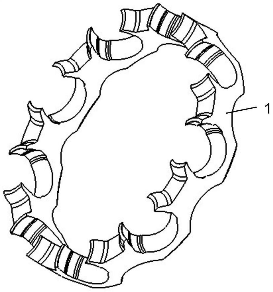
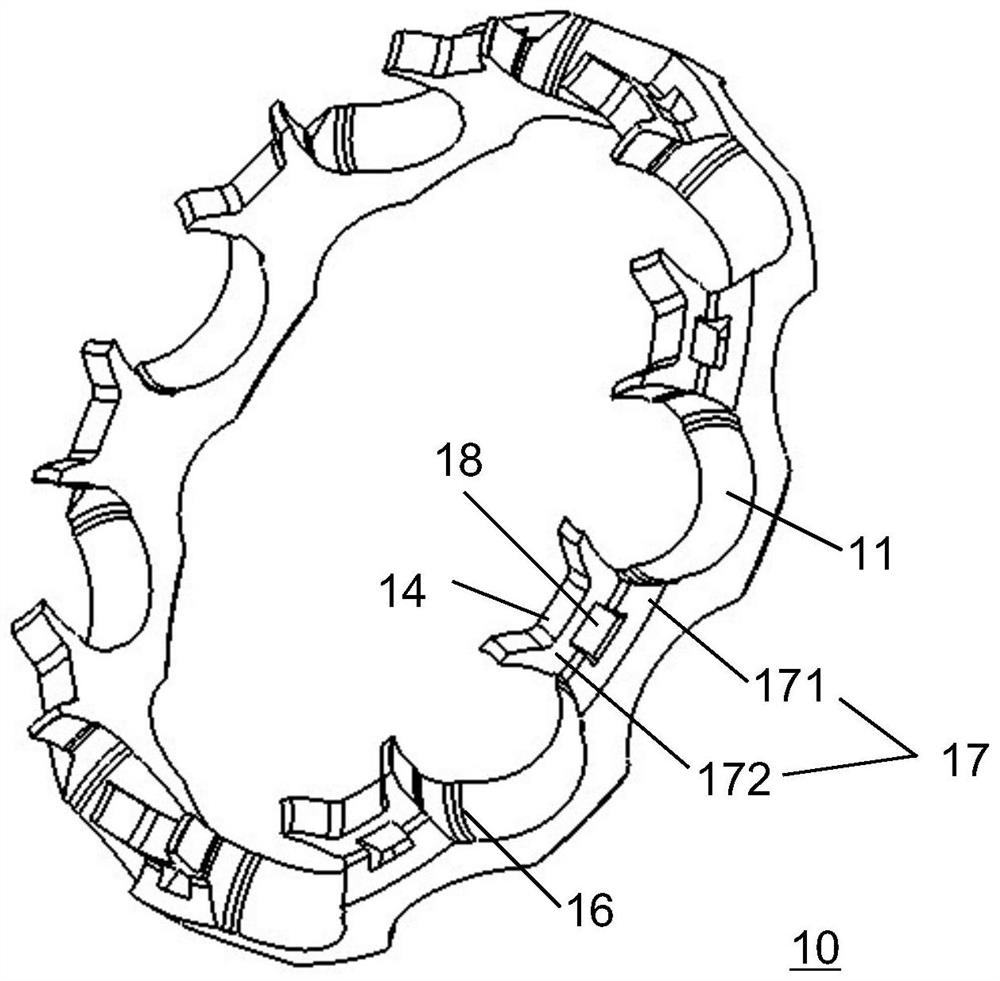
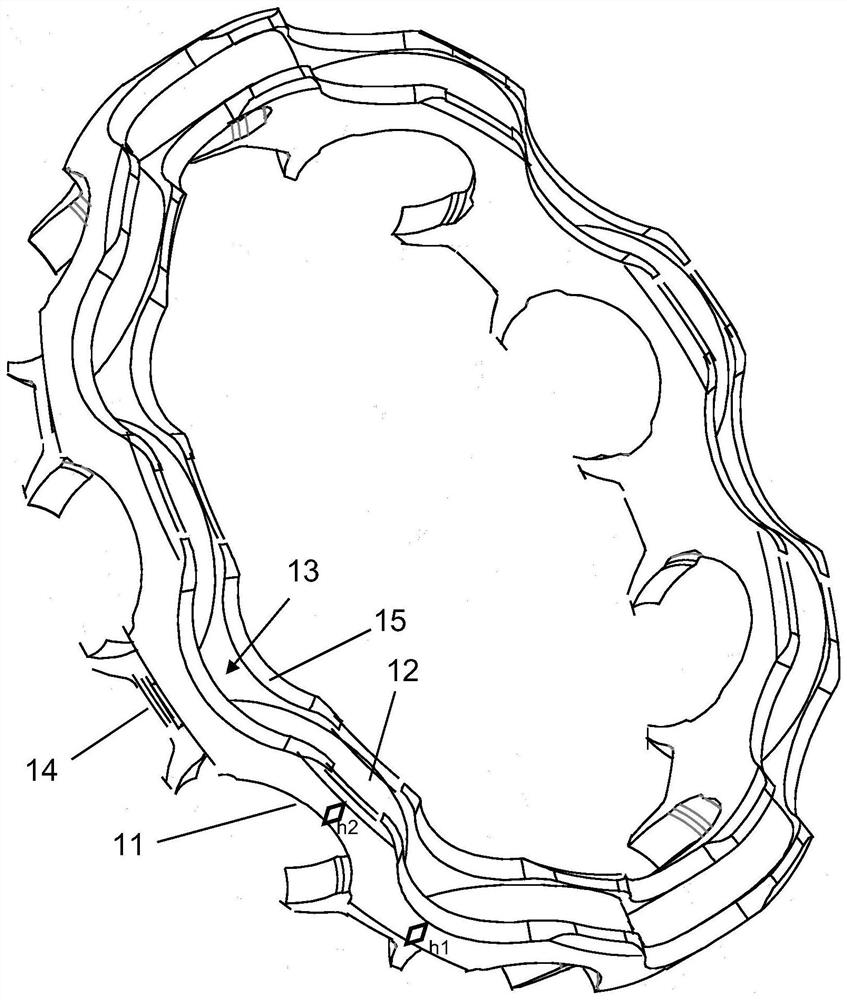
[0020] The high-speed bearing cage of the present invention is as Figure 2 to Figure 5 As shown, it is the same as the prior art in that it also includes an annular frame body 10, a plurality of pockets 11 evenly arranged on the upper end of the frame body 10, an annular groove 12 arranged at the bottom of the frame body 10, and pocket holes 11. The upper end forms an open jaw, and the bottom of the connection part 14 between two adjacent pocket holes 11 is provided with an upwardly concave arc surface 15, and each connection part 14 is provided with a grease chamber 13, and the grease container The bottom opening of the chamber 13 is located in the ring groove 12, and the middle positions of the inner surfaces on both sides of the pocket hole 11 are radially provided with an oil groove 16. Different from the prior art, the connecting portion 14 between two adjacent pocket holes 11 is designed as upper and lower parts. A cut-off step is formed, and the step has an oil guide ...


PUM


Abstract

The invention discloses a high-speed bearing retainer. The high-speed bearing retainer comprises a frame body, a plurality of pockets arranged at the upper end of the frame body and a ring groove formed in the bottom of the frame body, concave-up arc surfaces are arranged at the bottoms of connecting parts between every two adjacent pockets, lubricating grease accommodating cavities are formed inthe connecting parts, bottom openings of the lubricating grease accommodating cavities are located in the ring groove, and oil grooves are formed in the inner surfaces of the pockets. The connecting parts are divided into upper parts and lower parts, the lower parts have the same thickness as the frame body, the upper parts are thinner than the lower parts, and the upper parts and the lower partsforms a step outside the connecting parts, and oil guide holes communicating with the corresponding lubricating grease accommodating cavities on the lower part are formed in the step. According to thehigh-speed bearing retainer, through the design of the arc surfaces, the step and the oil guide holes, the high-speed bearing retainer has the advantages of reducing own weight, shifting up the center of mass and enhancing the lubricating effect while the strength of pocket claw mouths is ensured to the greatest extent, the weight is reduced, the lubricating effect is improved, the strength and stability of the pockets are ensured, and problems such as relatively large deformation are solved.

Description

technical field [0001] The invention belongs to a bearing cage, in particular to a high-speed bearing cage. Background technique [0002] Bearings are an important rotating support component in contemporary mechanical equipment. Its main function is to support the mechanical rotation, reduce friction during its movement, and ensure its rotation accuracy. The cage (that is, the bearing cage, also known as the bearing cage) refers to the bearing parts that partially wrap all or part of the rolling elements and move with them, to isolate the rolling elements, and usually guide the rolling elements and keep them in the bearing Inside. [0003] Existing high-speed bearing cages such as figure 1 As shown, its publication number is CN109027009A. The inner and outer diameters of the cage 1 are of uniform wall thickness. Bearings using this type of cage, because the inner and outer diameter surfaces of the cage and the inner and outer rib surfaces of the bearing The gap between t...

Claims


Application Information

Patent Timeline
Patent Type & Authority Applications(China)
IPC IPC(8): F16C33/38F16C33/66
CPCF16C33/38F16C33/6603F16C33/6629
Inventor 邓四二郑得印文绪明
Owner 马纯
Why Eureka
Try Eureka