
Engine braking castellation mechanism

A technology for structural components and engines, applied in engine components, machines/engines, mechanical equipment, etc., to solve problems such as slowing down vehicles

Active Publication Date: 2020-09-11
EATON INTELLIGENT POWER LTD
View PDF6 Cites 0 Cited by
  • Summary
  • Abstract
  • Description
  • Claims
  • Application Information

AI Technical Summary

Problems solved by technology

This causes the engine to act as a power-consuming air compressor, which slows down the vehicle

Method used


Image

  • Engine braking castellation mechanism
  • Engine braking castellation mechanism
  • Engine braking castellation mechanism

Examples


Embodiment Construction

[0041] Especially at low engine speeds, heavy-duty (HD) diesel engines require high braking power. Some HD diesel engines are configured with valve trains with valve bridges, and include single overhead cam (SOHC) and overhead valve (OHV) valve trains. The present disclosure provides high braking power without imposing high loads on the rest of the valve train, especially the pushrods and camshafts. In this regard, the present disclosure provides a configuration in which only one exhaust valve is opened during a braking event.

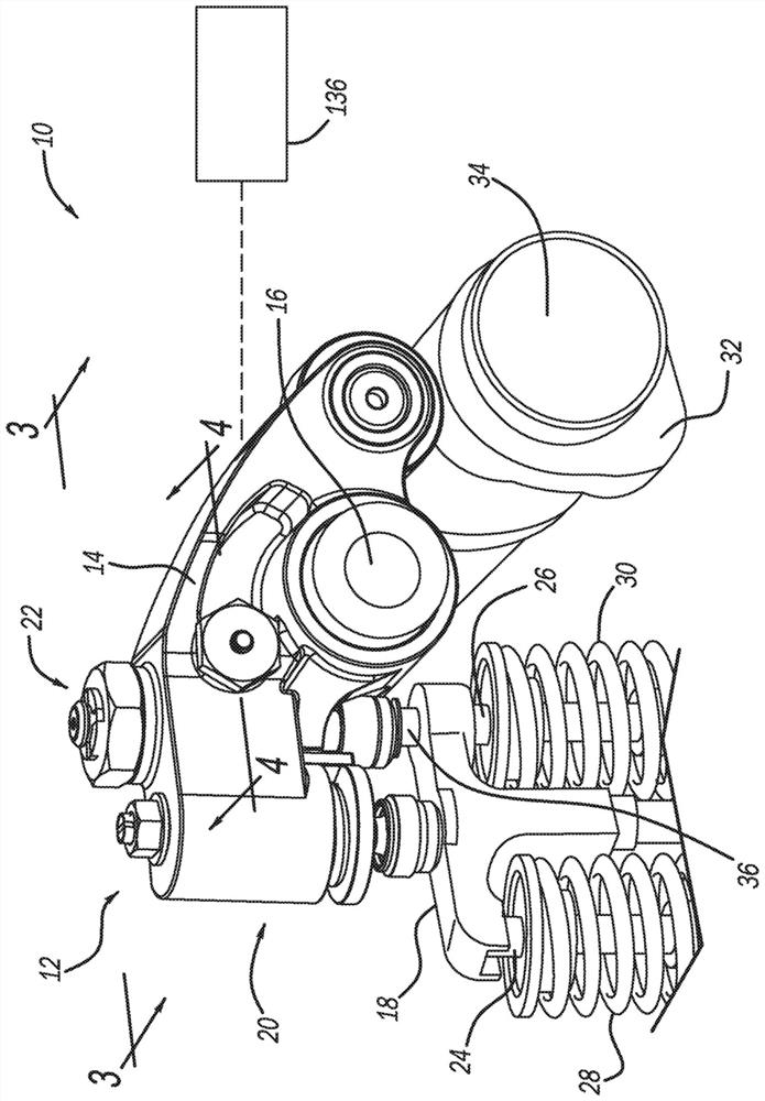
[0042] first reference figure 1 , shows a partial valve train assembly constructed in accordance with one example of the present disclosure and is generally identified as element numeral 10 . The partial valve train assembly 10 utilizes engine braking and is shown configured for use in a six cylinder engine. It should be understood, however, that the present teachings are not so limited. In this regard, the present disclosure may be used in any val...


PUM


Abstract

An engine brake rocker arm assembly is operable in an engine drive mode and an engine braking mode and selectively opens first and second exhaust valves. The engine brake rocker arm assembly includesan exhaust rocker arm configured to rotate about a rocker shaft, an engine brake capsule assembly movable between (i) a locked position configured to perform an engine braking operation, and (ii) an unlocked position that does not perform the engine braking operation, and a hydraulically controlled actuator assembly configured to selectively move the engine brake capsule assembly between the firstand second positions.

Description

[0001] Cross References to Related Applications [0002] This application claims the benefit of Indian Provisional Patent Application No. 201711047278 filed on December 29, 2017 and Indian Provisional Patent Application No. 201811007952 filed on March 3, 2018. The disclosures of the aforementioned applications are incorporated herein by reference. technical field [0003] The present disclosure relates generally to a rocker arm assembly for a valve train assembly, and more particularly to a rocker arm assembly having an engine brake bladder assembly actuated by a hydraulic actuator assembly. Background technique [0004] In addition to wheel brakes, compression engine brakes may be used as auxiliary brakes on relatively large vehicles such as trucks powered by heavy or medium duty diesel engines. The compression engine braking system is arranged to, when activated, provide additional opening of the exhaust valve of the cylinder of the engine when the piston in the cylinder ...

Claims


Application Information

Patent Timeline
Patent Type & Authority Applications(China)
IPC IPC(8): F01L13/06F01L13/00F01L9/02F01L9/10
CPCF01L2013/105F01L1/181F01L1/26F01L13/065F01L2800/10F01L2305/00F01L1/24F01L1/46F01L13/06F01L2001/467F02D13/04F01L9/10
Inventor 桑托什·帕蒂尔尼基尔·基肖尔·萨格姆马修·文斯
Owner EATON INTELLIGENT POWER LTD
Learn More