Multifunctional operation table equipment for factory

A multi-functional, console technology, applied in the direction of workbench, manufacturing tools, etc., can solve the problems of unfavorable sampling and unfavorable sampling equipment without better drones

Inactive Publication Date: 2020-09-15
于桂芝
View PDF0 Cites 1 Cited by
  • Summary
  • Abstract
  • Description
  • Claims
  • Application Information

AI Technical Summary

Problems solved by technology

[0002] In water conservancy sampling, there are some places with steep terrain, which is not conducive to sampling, and the UAV is flexible. However, there is no good sampling equipment under the UAV on the market, so this multi-functional UAV under-hung water conservancy sampling is designed. equipment

Method used


Image

  • Multifunctional operation table equipment for factory
  • Multifunctional operation table equipment for factory
  • Multifunctional operation table equipment for factory

Examples


specific Embodiment approach 1

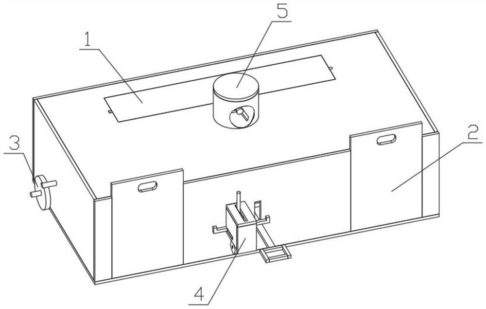
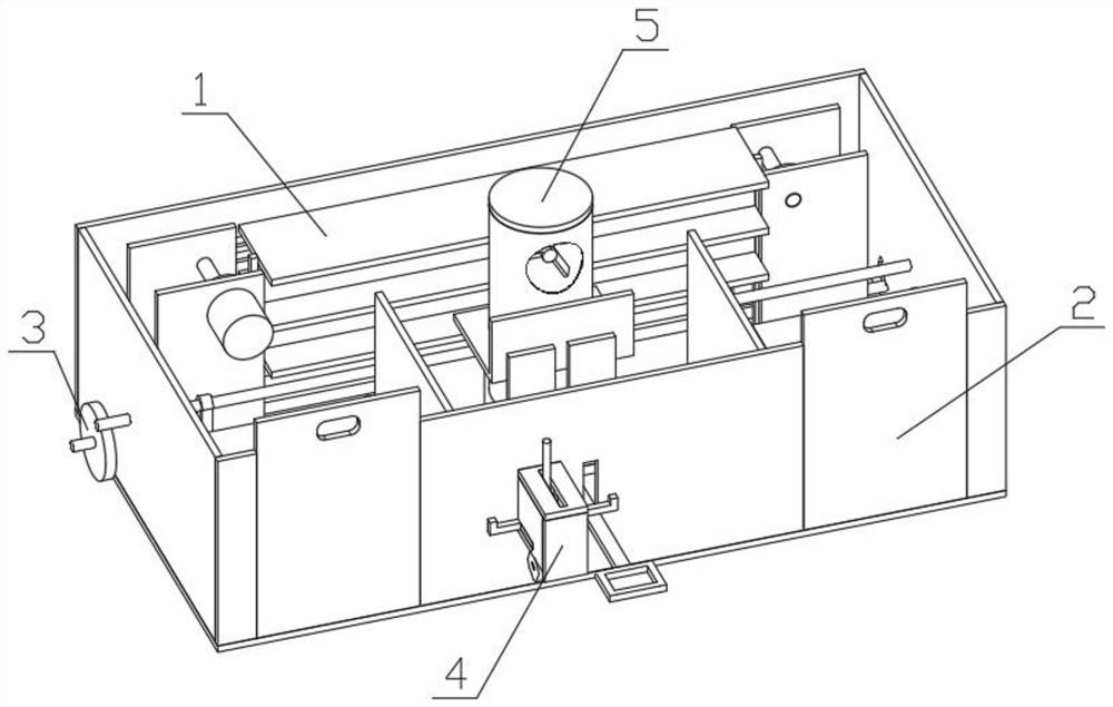
[0033] Combine below figure 1 , figure 2 , image 3 , Figure 4 , Figure 5 , Figure 6 , Figure 7 , Figure 8 , Figure 9 , Figure 10 , Figure 11 , Figure 12 , Figure 13 , Figure 14 , Figure 15 , Figure 16 , Figure 17 , Figure 18 To illustrate this embodiment, the present invention relates to a console device, more specifically a multifunctional console device for a factory, including a lifting tool table mechanism 1, a sliding chair mechanism 2, a traveling wheel mechanism 3, and a direction wheel mechanism 4 , Rotating dust suction mechanism 5, the equipment can automatically lift the tool table, the equipment can slide out of the chair, the equipment can automatically move, and the equipment can automatically suck the powder garbage on the operating table into the dust collection bucket.

[0034] The lifting tool table mechanism 1 is connected with the sliding chair mechanism 2, the traveling wheel mechanism 3 is connected with the lifting tool t...

specific Embodiment approach 2

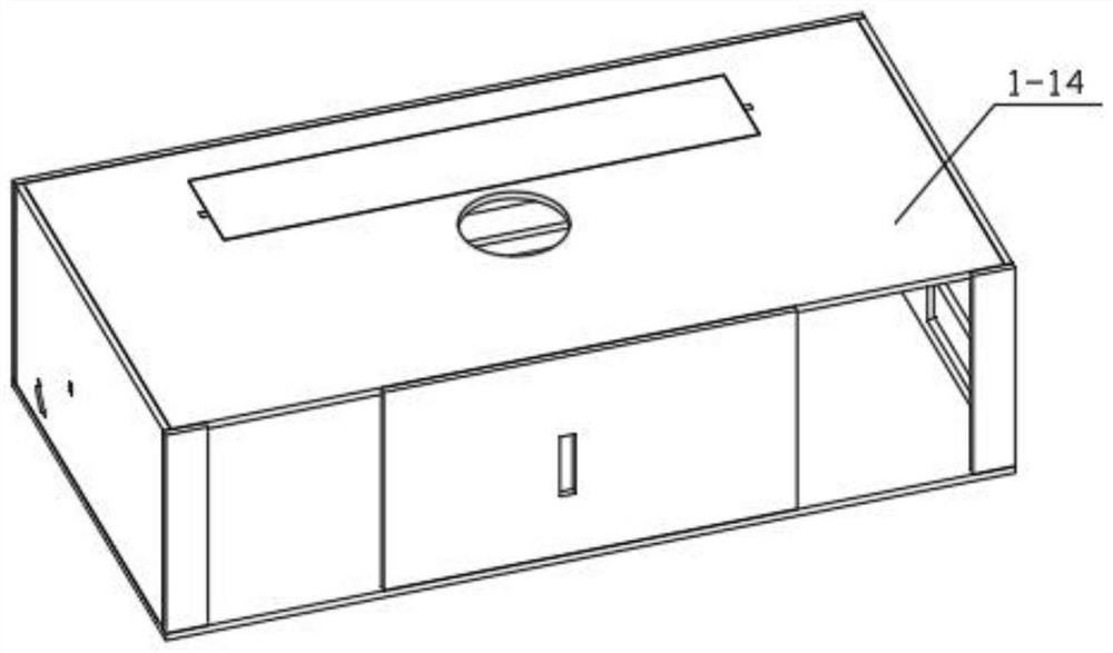
[0036] Combine below figure 1 , figure 2 , image 3 , Figure 4 , Figure 5 , Figure 6 , Figure 7 , Figure 8 , Figure 9 , Figure 10 , Figure 11 , Figure 12 , Figure 13 , Figure 14 , Figure 15 , Figure 16 , Figure 17 , Figure 18 Describe this embodiment, this embodiment will further explain Embodiment 1, the described elevating tool table mechanism 1 includes elevating motor 1-1, elevating transmission shaft 1-2, elevating belt 1-3, elevating gear 1-4, elevating Rack 1-5, tool table 1-6, mounting plate a1-7, mounting plate b1-8, mounting plate c1-9, mounting plate d1-10, mounting plate e1-11, mounting plate f1-12, mounting plate g1-13, mounting plate h1-14, the lifting motor 1-1 is connected with a lifting transmission shaft 1-2, the lifting transmission shaft 1-2 is frictionally connected with the lifting belt 1-3, the lifting gear 1-4 is connected with the lifting rack 1 -5 is meshed, the lifting rack 1-5 is connected to the tool table 1-6, the ...

specific Embodiment approach 3

[0038] Combine below figure 1 , figure 2 , image 3 , Figure 4 , Figure 5 , Figure 6 , Figure 7 , Figure 8 , Figure 9 , Figure 10 , Figure 11 , Figure 12 , Figure 13 , Figure 14 , Figure 15 , Figure 16 , Figure 17 , Figure 18 Describe this embodiment, this embodiment will further explain the first embodiment, the sliding chair mechanism 2 includes a ball shaft sliding groove 2-1, a sliding groove limiter 2-2, a ball shaft 2-3, and a ball shaft connecting shaft 2 -4, connecting plate a2-5, connecting plate b2-6, pulley shaft 2-7, pulley 2-8, pulley limit plate 2-9, connecting plate c2-10, connecting plate d2-11, connecting plate e2- 12. Connecting plate f2-13, connecting plate g2-14, the ball shaft sliding groove 2-1 is connected with the sliding groove limit 2-2, the ball shaft 2-3 is slidingly connected with the ball shaft sliding groove 2-1, and the ball shaft is connected The shaft 2-4 is connected with the ball shaft 2-3 bearing, the connec...


PUM


Abstract

The invention relates to operation table equipment, in particular to multifunctional operation table equipment for a factory. A lifting tool table mechanism, a sliding chair mechanism, an advancing wheel mechanism, a direction wheel mechanism and a rotation dust suction mechanism are included. The equipment can automatically lift a tool table, a chair can automatically slide out through the equipment, the equipment can automatically move, and the equipment can automatically suck dust garbage on an operation table into a dust suction barrel. The lifting tool table mechanism is connected with the sliding chair mechanism, the advancing wheel mechanism is connected with the lifting tool table mechanism, the direction wheel mechanism is connected with the lifting tool table mechanism, the rotation dust suction mechanism is connected with the lifting tool table mechanism, and the direction wheel mechanism is connected with the rotation dust suction mechanism.

Description

technical field [0001] The invention relates to a console device, more specifically a multifunctional console device for a factory. Background technique [0002] In water conservancy sampling, there are some locations with steep terrain, which is not conducive to sampling, and the UAV is flexible. However, there is no good sampling equipment under the UAV on the market, so this multi-functional UAV under-hung water conservancy sampling is designed. equipment. Contents of the invention [0003] The main technical problem to be solved by the present invention is to provide a multi-functional operating table equipment for factories, the equipment can automatically lift the tool table, the equipment can slide out of the chair, the equipment can automatically move, and the equipment can automatically suck and vacuum the powder garbage on the operating table inside the barrel. [0004] In order to solve the above technical problems, the present invention relates to a console d...

Claims


Application Information

Patent Timeline
IPC IPC(8): B25H1/00B25H1/16
CPCB25H1/00B25H1/16
Inventor 于桂芝
Owner 于桂芝
Why Eureka
Try Eureka