Multi-stage vibration reduction suspension structure

A suspension and hose technology, used in power units, jet propulsion units, internal combustion propulsion units, etc., can solve the problems of easy damage, single vibration reduction means, poor vibration reduction effect, etc., and achieve good vibration reduction effect and vibration reduction. Rich means to solve the effect of high high frequency dynamic stiffness

Active Publication Date: 2020-09-15
ZHEJIANG LEAPMOTOR TECH CO LTD
View PDF8 Cites 2 Cited by
  • Summary
  • Abstract
  • Description
  • Claims
  • Application Information

AI Technical Summary

Problems solved by technology

[0004] The present invention overcomes the disadvantages of single vibration damping means, poor vibration damping effect and easy damage of existing rubb

Method used


Image

  • Multi-stage vibration reduction suspension structure
  • Multi-stage vibration reduction suspension structure

Examples


Embodiment 1

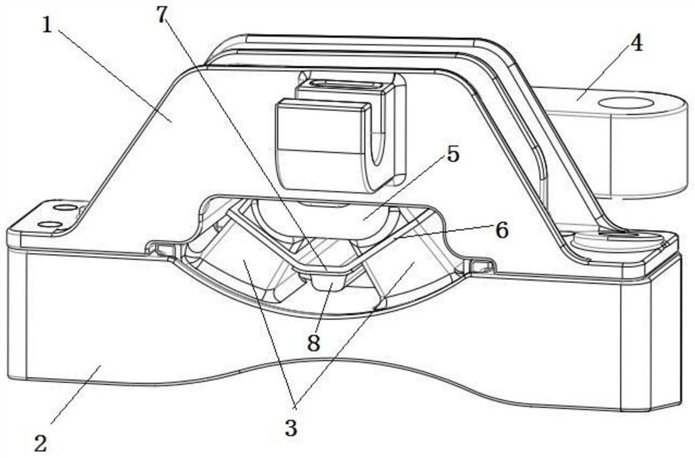
[0024] Such as figure 1 As shown, a multi-stage vibration-damping suspension structure includes an upper bracket 1, a lower bracket 2, a main spring rubber and a support arm 4 for connecting the engine assembly, and the main spring rubber includes a bracket for fixing the support arm The main spring inner frame 5 and two main spring bases 3 symmetrically arranged on both sides of the main spring inner frame, the middle part of the main spring rubber is provided with a vulcanized middle frame, and the vulcanized middle frame includes two left and right symmetrically arranged side plates 6 and the bottom plate 7 located between the side plates 6, the side plate 6 is embedded in one end of the main spring base 3 adjacent to the inner frame 5 of the main spring, and a columnar spacer rubber block 8 is provided under the bottom plate 7, the main spring There is a first gap between the spring inner frame 5 and the side plate 6 , and there is a second gap between the limiting rubber ...

Embodiment 2

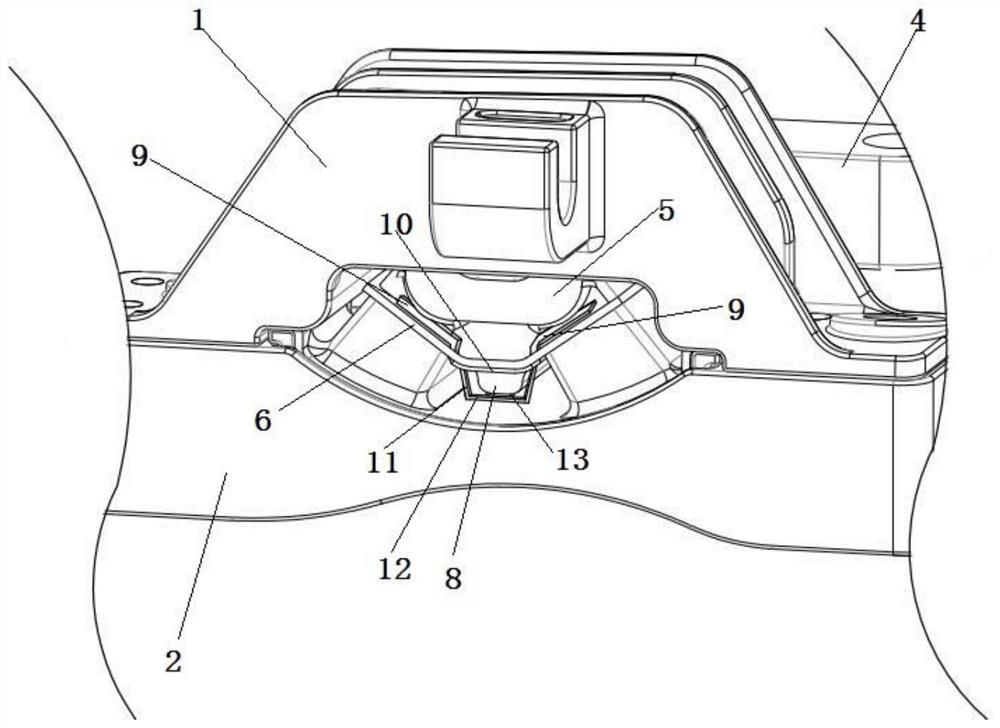
[0027] Based on Example 1, such as figure 2As shown, a first hose 9 is provided between the main spring inner frame 5 and the two side plates 6, and a second horizontal hose 10 is provided between the bottom plate 7 and the stop rubber block 8 , the second hose 10 is located between the two first hoses 9 and communicates with the first hose 9, and the two ends of the first hose 9 and the second hose 10 are connected to form a closed cavity. Hydraulic oil is provided inside the first hose 9 and the second hose 10 . Both sides of the second hose 10 are provided with a vertically arranged third hose 11, the upper end of the third hose 11 is connected to the bottom of the second hose 10 and a rubber valve (not shown in the figure) is provided at its upper port. , the rubber valve used will open when the rubber valve is squeezed by the hydraulic oil, and the rubber valve will close when there is no force), the fourth hose 12 placed horizontally is arranged under the limit rubber ...


PUM


Abstract

The invention discloses a vibration reduction suspension structure, and aims to provide a multi-stage vibration reduction suspension structure which is rich in vibration reduction means, good in vibration reduction effect and durable. The multi-stage vibration reduction suspension structure comprises an upper support, a lower support, main spring rubber and a supporting arm which is used for connecting an engine assembly; the main spring rubber comprises a main spring inner framework used for fixing the supporting arm and two main spring bases arranged on the two sides of the main spring innerframework in a bilateral symmetry mode; a vulcanized middle framework is arranged in the middle of the main spring rubber; the vulcanized middle framework comprises two side plates arranged in a bilateral symmetry mode and a bottom plate located between the side plates; the side plates are embedded in the ends, close to the main spring inner framework, of the main spring bases; a columnar limiting rubber block is arranged below the bottom plate; first gaps exist between the main spring inner framework and the side plates; and a second gap exist between the limiting rubber block and the lowersupport. With the multi-stage vibration reduction suspension structure adopted, multi-stage vibration isolation can be achieved, the problem that the high-frequency dynamic stiffness of a pure rubbersuspension is too high is solved, and NVH performance is optimized.

Description

technical field [0001] The invention relates to the technical field of automobile engine vibration reduction, in particular to a multi-stage vibration reduction suspension structure. Background technique [0002] Rubber mount is a commonly used vibration damping mechanism for automobile engines. However, the existing pure rubber mount is easy to harden in high-frequency dynamic stiffness (high-frequency dynamic hardening degree), and the low-frequency large limit rigidity is very prominent, resulting in powertrain The problem of NVH is more serious. [0003] Chinese Patent Publication No. CN205818917U, the publication date is December 21, 2016. The name of the invention is rubber suspension and automobile. The application discloses a rubber suspension and automobile, which involves powertrain installation technology. The rubber suspension includes: a first rubber main spring and a second rubber main spring; the first rubber main spring is arranged between the support arm an...

Claims


Application Information

Patent Timeline
IPC IPC(8): B60K5/12
CPCB60K5/1275
Inventor 李建华杨志伟季明孙钢宫静董炜
Owner ZHEJIANG LEAPMOTOR TECH CO LTD
Why Eureka
Try Eureka