
Engine

A technology of engine and transmission wheel, which is applied in the direction of engine components, combustion engines, engine starting, etc., and can solve problems such as difficult control, easy flameout, and large supercharged structure

Pending Publication Date: 2020-09-15
ENTROPY ZERO TECH LOGIC ENG GRP CO LTD
View PDF0 Cites 2 Cited by
  • Summary
  • Abstract
  • Description
  • Claims
  • Application Information

AI Technical Summary

Problems solved by technology

[0002] The crankshaftless cylinder piston engine has the characteristics of high efficiency, simple structure, less friction pairs, good environmental protection, and strong fuel diversity, etc., but its practical application has been limited. Mechanical supercharging, and the supercharging structure is huge and difficult to control

Method used


Image

  • Engine
  • Engine
  • Engine

Examples


Embodiment 1

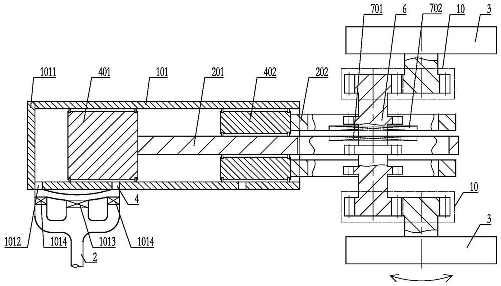
[0057] an engine such as figure 1As shown, it includes a cylinder A 101, a reciprocating structure A 201 and a reciprocating structure B 202, a piston A 401 is set on the reciprocating structure A 201, and a piston B is set on the reciprocating structure B 202 402, the piston A 401 and the piston B 402 are arranged on top of each other in the cylinder A 101, and the reciprocating structure A 201 is partially arranged in the cylinder A 101 and passes through the piston B 402. The gas distribution port 4 is set on the cylinder A 101, the reciprocating structure A 201 and the reciprocating structure B 202 are set in reverse linkage through the transmission wheel 6, and the cylinder A 101 includes a cylinder A end 1011, so The piston A 401, the side wall of the cylinder A 101 and the end 1011 of the cylinder A form a volume change space, and a gas conduction port A 1012 is set on the side wall of the cylinder A 101, and the gas conduction port A 1012 It is set in communication wi...

Embodiment 2

[0064] an engine such as figure 2 As shown, the difference with Embodiment 1 is that on the basis of Embodiment 1, the two ends of the transmission wheel 6 are further set through the transmission unit 10 and the mass of inertia 3 respectively, and the reciprocating structure A201 A magnetic zone A 701 is set on the reciprocating structure B 202, and a magnetic zone B 702 is set on the reciprocating structure B 202. The magnetic zone A701 and the magnetic zone B 702 are mutually magnetically arranged.

[0065] As an alternative embodiment, in Embodiment 2 of the present invention, the magnetic force interaction setting between the magnetic force zone A 701 and the magnetic force zone B 702 and the magnetic force zone X can also be selectively selected.

[0066] As a transformable embodiment, in embodiment 2 of the present invention and its transformable embodiments, it is preferable to make the transmission unit 10 as a speed change mechanism or as a torsion bar during specif...

Embodiment 3

[0069] an engine such as image 3 As shown, the difference from Embodiment 1 is that on the basis of Embodiment 1, the transmission wheel 6 is further configured to be driven by the elastic structure body 13 and the moment of inertia body 3 .

[0070] As a transformable embodiment, the transformable embodiment of the embodiment 1 of the present invention can further selectively make the transmission wheel 6 and the moment of inertia body 3 drive and set through the elastic structure body 13 . Preferably, the elastic structure 13 is a torsion bar. For specific implementation, it can be implemented with reference to the implementation manner of Example 3.


PUM


Abstract

The invention discloses an engine. The engine comprises an air cylinder A, a reciprocating motion structural body A and a reciprocating motion structural body B. A piston A arranged on the reciprocating motion structural body A and a piston B arranged on the reciprocating motion structural body B are oppositely arranged in the air cylinder A. The reciprocating motion structural body A is arrangedin the air cylinder A and penetrates through the piston B, and an air distribution opening is formed in the air cylinder A. The reciprocating motion structure body A and the reciprocating motion structure body B are arranged in a reverse linkage mode through a transmission wheel, and a volume change space is defined by the piston A, the side wall of the air cylinder A and the end of the air cylinder A. An air guide opening A is formed in the side wall of the air cylinder A. The air guide opening A directly communicates with the air distribution opening of the air cylinder A. The air guide opening A communicates with a gas inlet channel through a one-way switch, and the air guide opening A communicates with the gas inlet channel through the control switch. The engine is not prone to flameout, good in continuous working performance, capable of effectively breaking through limitation of a crankshaft-free air cylinder piston engine, simple in structure and convenient to control.

Description

technical field [0001] The invention relates to the field of thermal energy and power, in particular to an engine. Background technique [0002] The crankshaftless cylinder piston engine has the characteristics of high efficiency, simple structure, less friction pairs, good environmental protection, and strong fuel diversity, etc., but its practical application has been limited. Supercharging, and the supercharging structure is huge and difficult to control. Therefore need to invent a kind of good novel engine of continuous duty. Contents of the invention [0003] In order to solve the above problems, the technical scheme proposed by the present invention is as follows: [0004] Scheme 1: An engine comprising a cylinder A, a reciprocating structure A and a reciprocating structure B, a piston A is arranged on the reciprocating structure A, a piston B is arranged on the reciprocating structure B, and the The piston A and the piston B are arranged in the cylinder A facing ...

Claims


Application Information

Patent Timeline
IPC IPC(8): F02B75/28F02B75/32F02B75/24F02B63/04F02B33/42F02N15/00
CPCF02B33/42F02B63/04F02B75/24F02B75/28F02B75/32F02N15/00
Inventor 靳北彪
Owner ENTROPY ZERO TECH LOGIC ENG GRP CO LTD
Learn More