Frequency locking method of plasma power

A plasma and frequency-locking technology, applied in the field of ion source, can solve the problems that the high-frequency phase cannot be completely and accurately positioned, the working state cannot be completely matched, and the volume cannot be achieved, achieving high power stability, not easy to flame out, and saving The effect of electricity

Active Publication Date: 2015-04-29
FOCUSED PHOTONICS
View PDF6 Cites 0 Cited by
  • Summary
  • Abstract
  • Description
  • Claims
  • Application Information

AI Technical Summary

Problems solved by technology

Among them, the excitation type is a fixed frequency, and the stepping motor is used to adjust and match the vacuum adjustable capacitor to match the load. This method requires a precise stepping motor and a vacuum adjustable capacitor, which has high cost, large volume, and low efficiency. Since the stepping motor is a mechanical movement, its dynamic response is slow; in addition, there are two methods for the self-excited type: one is to detect the reflected power method, use the stepping motor to roughly adjust the matching box, and then adjust the frequency according to the reflected power. The matching box is still needed, its volume is large, and the dynamic response is slightly improved, but it is still relatively poor; another method is direct coupling, which detects the output phase and input phase, and performs feedback to adjust the frequency according to the phase difference. This technology is relatively advanced. The technology is monopolized by a few foreign companies. Its efficiency is relatively high and its volume is relatively small. However, because the high-frequency phase cannot be completely and accurately positioned, its working state cannot reach a complete matching state, but can only be close to a complete matching state, and its volume cannot be minimized. Efficiency can not be the highest

Method used


Image

  • Frequency locking method of plasma power
  • Frequency locking method of plasma power

Examples


Embodiment 1

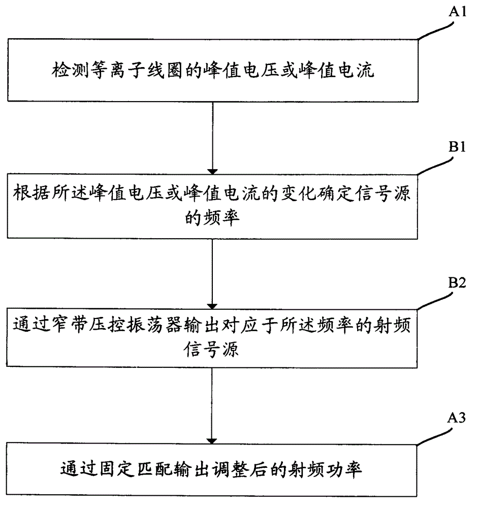
[0033] figure 1 The flow diagram of the frequency locking method of the plasma power supply in the embodiment of the present invention is schematically provided, as figure 1 As shown, the frequency locking method includes the following steps:

[0034] (A1) Detect the peak voltage or peak current of the plasma coil; preferably, use an induction coil to detect the peak voltage or peak current.

[0035] (A2) Adjust the frequency of the signal source according to the change of the peak voltage or peak current; preferably, the step (A2) further includes:

[0036] (B1) Determine the frequency of the signal source according to the change of the peak voltage or peak current; preferably, in the step (A2), the adjustment method is specifically:

[0037] When the peak voltage or peak current detected this time is increased compared with that detected last time, increasing the frequency of the signal source;

[0038] When the peak voltage or peak current detected this time is smaller t...

Embodiment 2

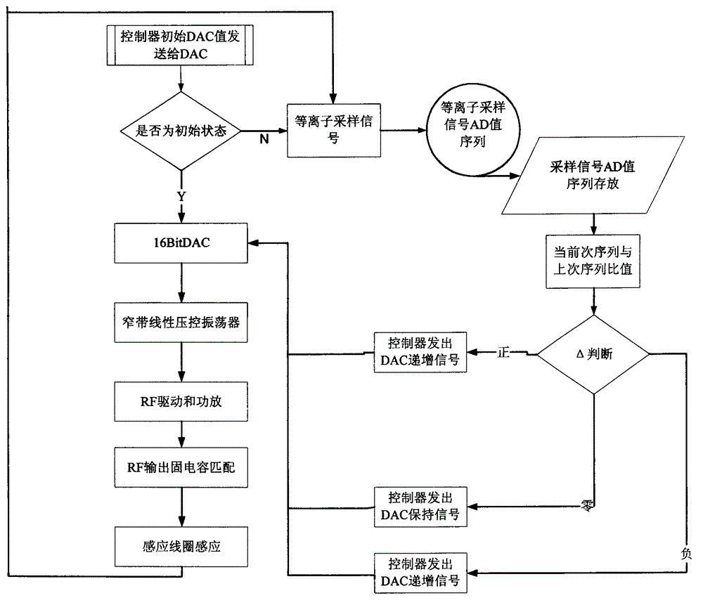
[0043] An application example of the plasma power supply frequency locking method in ICP-MS according to Embodiment 1 of the present invention.

[0044] figure 2 A flow chart of the frequency locking method of the plasma power supply according to the embodiment of the present invention is schematically provided, as figure 2 As shown, the radio frequency method comprises the following steps:

[0045] The controller transmits the initial value of the digital-to-analog converter to the 16-bit digital-to-analog converter;

[0046] The digital-to-analog converter judges whether it is an initial state, and if the judgment result is yes, the digital-to-analog converter outputs a signal to a narrowband linear voltage-controlled oscillator, and the bandwidth of the narrowband is [f 0 -3MHz, f 0 +3MHz], the f 0 The center frequency is 27.12MHz;

[0047] The output signal of the oscillator is applied to the plasma coil through a fixed capacitance matching circuit after being drive...


PUM


Abstract

The invention provides a frequency locking method of plasma power. The frequency locking method includes the following steps: (A1) detecting peak voltage or peak current of a plasma coil, (A2) adjusting frequency of a signal source according to the peak voltage or the peak current, and (A3) outputting adjusted radio frequency power through fixed matching. The frequency locking method of the plasma power has the advantages of being high in efficiency, very little in outward radiation, good in work stability, high in reliability, capable of continuously adjusting the output frequency and zero reflection power and the like.

Description

technical field [0001] The invention relates to a plasma source, in particular to a frequency-locking method for a plasma power supply. Background technique [0002] In ICP-AES and ICP-MS products, adjustable high-power RF plasma power supplies are required. Domestic high-power RF power supplies are large in size, high in cost, low in efficiency, and poor in reliability; while the most advanced foreign technologies are monopolized by very few companies. At present, there are mainly the following modes of RF plasma power supply: self-excited RF power amplifier plus matching box, self-excited RF power amplifier plus matching box, and self-excited direct coupling. Among them, our company adopts a self-excited direct-coupled RF plasma power supply. The core of the realization of the self-excited RF power supply is the feedback technology. At present, there are: power feedback and phase feedback. What we use is to detect the output peak voltage and current, and use the Δ intelli...

Claims


Application Information

Patent Timeline
Patent Type & Authority Patents(China)
IPC IPC(8): H05H1/46
Inventor 郑新平张涛张建寿淼均喻正宁沈旭胡杰夏晓峰
Owner FOCUSED PHOTONICS
Why Eureka
Try Eureka