

Heavy truck curve anti-rollover early warning system
An early warning system and technology for heavy trucks, applied in the direction of road vehicle traffic control system, traffic control system, radio wave measurement system, etc. The early warning program is scientific and flexible, corrects bad driving habits, and calculates the effect accurately
- Summary
- Abstract
- Description
- Claims
- Application Information
AI Technical Summary
Problems solved by technology
Method used
Image

Examples
Embodiment Construction
[0023] The present invention will be described in detail below in conjunction with the accompanying drawings and embodiments.
[0024] The present invention comprises the following steps:
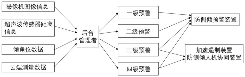
[0025] 1) Set up an anti-rollover early warning system for heavy truck curves, which includes an anti-roll measurement device, an anti-roll early warning device, an anti-roll man-machine collaboration device and an anti-roll cloud computing connection device.
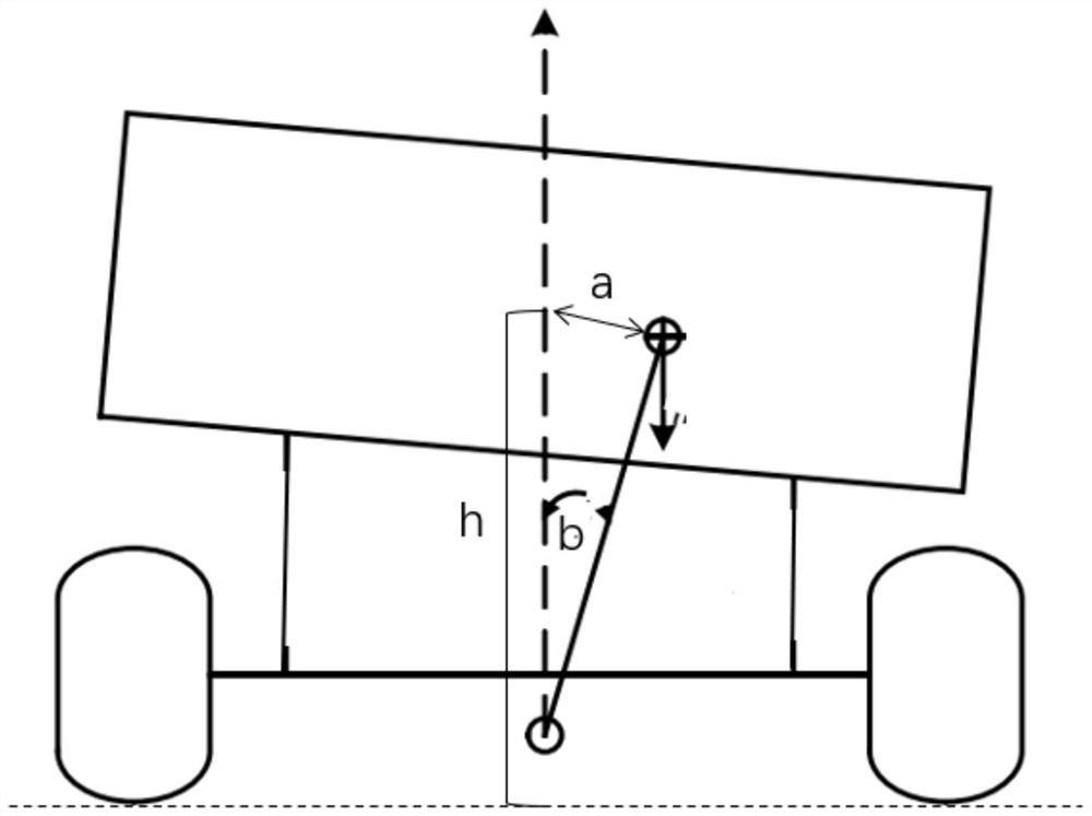
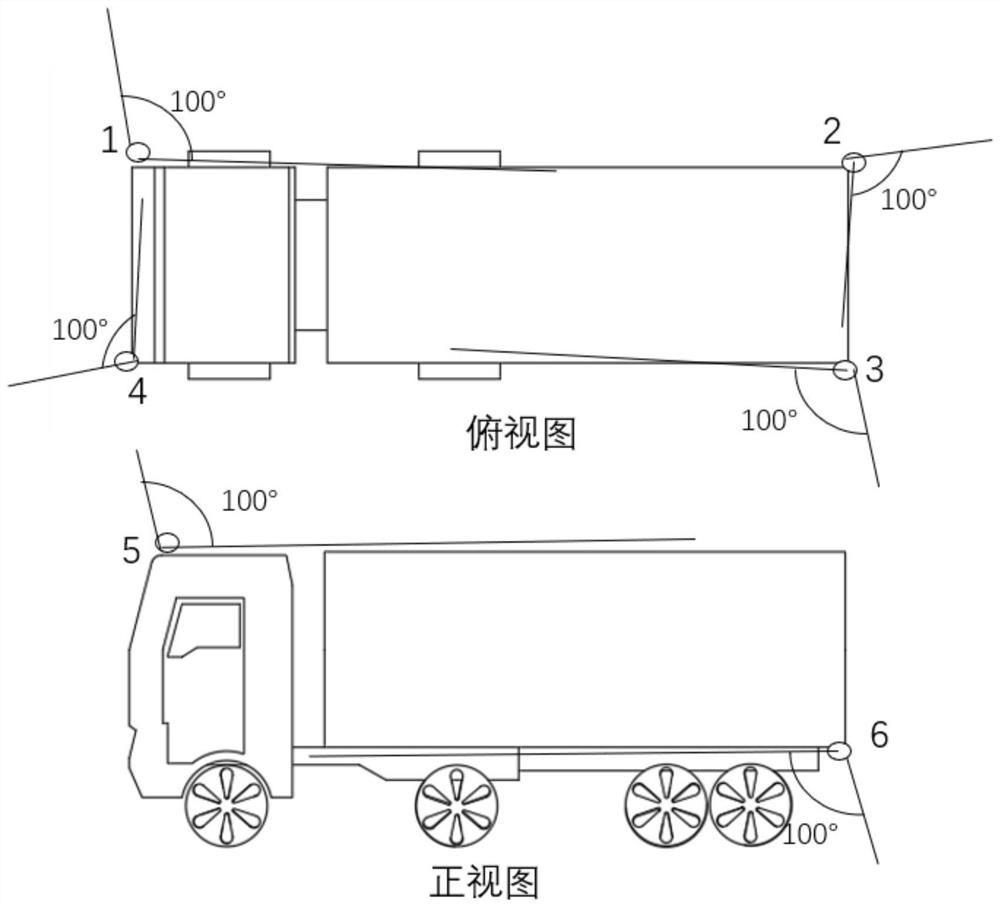
[0026] 2) Use the camera to capture information such as road slope width and obstacles around the vehicle, and combine the vehicle roll angle measured by the inclinometer, the curvature of the curve and the height of the center of mass measured by the cloud to calculate the vehicle roll acceleration, and estimate the roll warning time and side Leaning towards neighboring vehicles affects the result.
[0027] 3) According to the camber angle of the wheel, the offset distance of the center of mass and the inclination angle of the car,...
PUM
 Abstract
Description
Claims
Application Information