Transformer protection device based on electromagnetic induction principle

A transformer protection and electromagnetic induction technology, applied in the field of transformers, can solve problems such as insufficient output voltage monitoring and protection, increased transformer maintenance costs, poor heat dissipation of transformers, etc., achieve flexible temperature protection methods, increase heat dissipation methods, and protect the operating temperature environment Effect

Inactive Publication Date: 2020-09-15
陈太保
View PDF0 Cites 2 Cited by
  • Summary
  • Abstract
  • Description
  • Claims
  • Application Information

AI Technical Summary

Problems solved by technology

[0003] The amount of current that the transformer allows to pass continuously in the voltage transmission line without overheating the wire is called the safe carrying capacity or safe current, and during the voltage application process, the continuous internal high temperature environment seriously affects the service life of the transformer. However, the existing When the transformer is working, it often only monitors and protects the input motor, and the monitoring and protection of the output voltage is insufficient, and the existing transformer has poor heat dissipation effect and single heat dissipation function, which leads to the low service life of the existing transformer and limits the existing Transformer maintenance costs increase

Method used


Image

  • Transformer protection device based on electromagnetic induction principle
  • Transformer protection device based on electromagnetic induction principle
  • Transformer protection device based on electromagnetic induction principle

Examples


Embodiment Construction

[0026] The following will clearly and completely describe the technical solutions in the embodiments of the present invention with reference to the accompanying drawings in the embodiments of the present invention. Obviously, the described embodiments are only some, not all, embodiments of the present invention. Based on the embodiments of the present invention, all other embodiments obtained by persons of ordinary skill in the art without making creative efforts belong to the protection scope of the present invention.

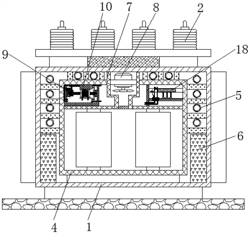
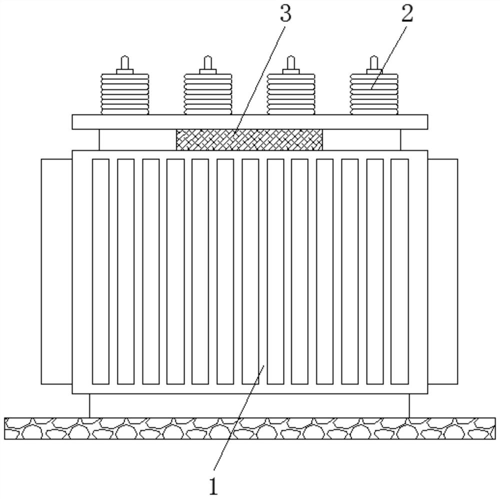
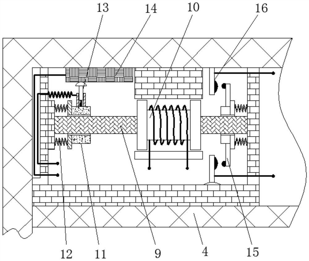
[0027] see Figure 1-4 , a transformer protection device based on the principle of electromagnetic induction, including an outer box 1, a terminal post 2, a vent 3, an inner box 4, a heat dissipation pipe 5, an oil pump 6, an air duct 7, a fan 8, a positioning rod 9, an electromagnetic Iron 10, movable block 11, back-moving spring 12, contact rod 13, resistance block 14, connecting rod 15, control sheet 16, bimetal sheet 17, push block 18, plectrum 19, fixed s...


PUM


Abstract

The invention relates to the technical field of transformers. The invention further discloses a transformer protection device based on the electromagnetic induction principle. The device comprises anouter box, the top of the outer box body is fixedly connected with a binding post; a ventilation opening is formed in the top of the side surface of the outer box body; an inner box body is fixedly connected to the interior of the outer box body; the outer portion of the inner box body is movably connected with a heat dissipation pipe; an oil pump is fixedly connected to the outer part of the heatdissipation pipe; a ventilating duct is formed in the inner box body; a fan is fixedly connected to the interior of the ventilating duct; a positioning rod is fixedly connected to the interior of theinner box body; through the cooperative use of the heat dissipation pipe, the oil pump, the ventilation duct and the draught fan, the heat dissipation effect of the transformer is effectively guaranteed, the heat dissipation mode of the transformer is increased, the working temperature of the transformer is guaranteed, the aging of transformer parts is avoided, the service life of the transformeris effectively prolonged, fire disasters caused by too high temperature are effectively avoided, and therefore, the safety of a circuit is protected.

Description

technical field [0001] The invention relates to the technical field of transformers, in particular to a transformer protection device based on the principle of electromagnetic induction. Background technique [0002] The transformer is a device that uses the principle of electromagnetic induction to change the AC voltage. The main components are the primary coil, the secondary coil and the iron core (magnetic core). The main functions are: voltage conversion, current conversion, impedance conversion, isolation, voltage stabilization (magnetic Saturated transformers), etc., can be divided into: power transformers and special transformers (electric furnace transformers, rectifier transformers, power frequency test transformers, voltage regulators, mining transformers, audio transformers, intermediate frequency transformers, high frequency transformers, impact transformers, instrument with transformers, electronic transformers, reactors, transformers, etc.). [0003] The amoun...

Claims


Application Information

Patent Timeline
Patent Type & Authority Applications(China)
IPC IPC(8): H01F27/02H01F27/08H01F27/14H01F27/22H01F27/40
CPCH01F27/02H01F27/08H01F27/14H01F27/22H01F27/40
Inventor 陈太保
Owner 陈太保
Why Eureka
Try Eureka