A foldable and portable dual-mode ultra-wideband omnidirectional antenna

An ultra-wideband, omnidirectional antenna technology, applied in the field of foldable portable dual-mode ultra-wideband omnidirectional antenna, can solve the problems of ultra-wideband antenna fission, inability to effectively realize communication, etc., to solve serious distortion and improve radiation pattern. Features, Effects that Reduce Influence

Active Publication Date: 2021-07-20
XIAN XINGWANG ANTENNA TECH
View PDF9 Cites 0 Cited by
  • Summary
  • Abstract
  • Description
  • Claims
  • Application Information

AI Technical Summary

Problems solved by technology

In order to solve the problem that the ultra-wideband antenna has a fission pattern in the high-frequency band and cannot effectively realize communication, the present invention proposes a dual-mode working system: specifically, in the low-frequency band, the working mode of the antenna is basically the same as that of the original wide-band antenna, which is still In the monopole form, the radiation pattern of the antenna is omnidirectional and the horizontal plane is the largest; in the high frequency band, the antenna working mode becomes a dipole form, and the antenna radiation pattern is similar to the standard dipole antenna pattern at this time, ensuring that the antenna pattern is completely Characteristic of maximum radiation in azimuth and horizontal planes

Method used


Image

  • A foldable and portable dual-mode ultra-wideband omnidirectional antenna
  • A foldable and portable dual-mode ultra-wideband omnidirectional antenna
  • A foldable and portable dual-mode ultra-wideband omnidirectional antenna

Examples


Embodiment Construction

[0041] The present invention will be described in further detail below in conjunction with the accompanying drawings and embodiments. It should be understood that the specific embodiments described here are only used to explain the present invention, not to limit the present invention.

[0042] figure 1 It is a structural schematic diagram of a foldable portable dual-mode ultra-wideband omnidirectional antenna according to an embodiment of the present invention.

[0043] like figure 1 As shown, a foldable portable dual-mode ultra-wideband omnidirectional antenna includes:

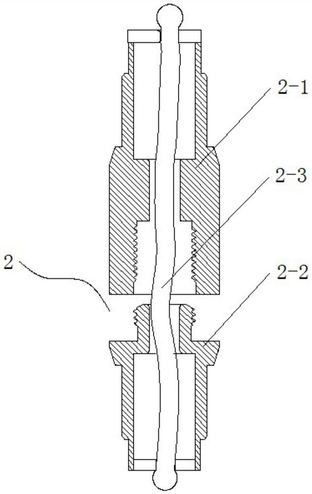
[0044] Upper antenna 1, connecting sleeve 2, steering gear assembly 3 and base 4;

[0045] The upper antenna 1 includes a steel strip 1-2, a steel strip connector 1-3, a coil 1-4, and an outer conductor tube 1-5 from top to bottom; the cross section of the steel strip 1-2 is arc-shaped, and its arch The raised side is set outward, and the steel strip 1-2 is fixed with a special heat-shrinkable tube 1-6;...


PUM


Abstract

The invention provides a foldable and portable dual-mode ultra-wideband omnidirectional antenna, comprising: an upper antenna, a connecting sleeve, a steering assembly and a base, and the two ends of the steering assembly are respectively connected with the base and the connecting sleeve; the upper antenna includes a steel Strip, steel strip connector, coil and outer conductor tube, the two ends of the steel strip connector are respectively connected to the steel strip and the coil; the connecting sleeve includes an upper connecting sleeve and a lower connecting sleeve; the outer conductor tube is provided with a rigid wire , the upper end of the rigid wire is connected to the coil, and the lower end is connected to the lower end of the outer conductor tube and the upper connecting sleeve; the steering assembly includes a gooseneck and a broadband matcher; the base includes a radio frequency connector and an antenna choke. The dual-mode working system proposed by the present invention successfully solves the problem that the existing ultra-wideband antenna has fission in the high-frequency pattern and cannot effectively realize communication; at the same time, it is convenient to fold, easy to carry, bendable and steerable, and has strong practicability.

Description

technical field [0001] The invention belongs to the technical field of communications and antennas, and in particular relates to a foldable and portable dual-mode ultra-wideband omnidirectional antenna. Background technique [0002] In radio equipment, the device used to radiate and receive radio waves is called an antenna. Like transmitters and receivers, antennas are also an important part of radio equipment. With the rapid development of modern communication technology, the frequency band of radio communication is getting wider and wider. From the original single-frequency point and broadband communication to multi-frequency point and ultra-wideband communication technology, the latest ultra-wideband communication frequency bandwidth has reached A dozen or even thirty octaves. In response to this demand, the corresponding antenna operating bandwidth has also been rapidly expanded, requiring coverage of more than a dozen or even dozens of octaves. Although the impedance...

Claims


Application Information

Patent Timeline
Patent Type & Authority Patents(China)
IPC IPC(8): H01Q25/04H01Q1/36H01Q1/08H01Q1/12H01Q1/52H01Q1/24
CPCH01Q1/08H01Q1/12H01Q1/241H01Q1/36H01Q1/52H01Q25/04
Inventor 张辉毛子强岳正鹏赵云滕强
Owner XIAN XINGWANG ANTENNA TECH
Why Eureka
Try Eureka