Mounting head assembly, chip mounter and chip mounting method
A chip mounter and head-mounting technology, applied in the direction of electrical components, electrical components, etc., can solve the problems of unfavorable heat dissipation, repair and maintenance, and increase the overall equipment manufacturing cost, so as to facilitate heat dissipation and later maintenance, increase maintenance costs, and reduce usage The effect of longevity
- Summary
- Abstract
- Description
- Claims
- Application Information
AI Technical Summary
Problems solved by technology
Method used
Image

Examples
Embodiment 1
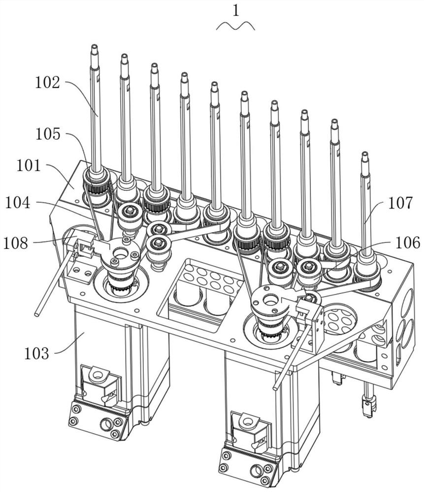
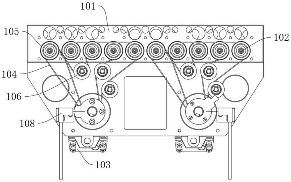
[0077] In this embodiment, m=2, and there are two rotating motors 103 and ten mounting heads 102 , and each rotating motor 103 controls five mounting heads 102 to rotate.
[0078] The same rotating motor 103 is connected with two driving belts 104, which are respectively the first driving belt and the second driving belt, and all the mounting heads 102 driven by the same rotating motor 103 are marked as the first mounting head, the second mounting head, and the second driving belt in one direction. The placement head, the third placement head, the fourth placement head and the fifth placement head are divided into the first group of placement heads and the second group of placement heads.
[0079] The first placement head, the second placement head and the third placement head can be used as the first placement head, and the fourth placement head and the fifth placement head can be used as the second placement head ;It is also possible to use the first placement head, the seco...
Embodiment 2
[0095] In this embodiment, m=2, and there are two rotating motors 103 and twelve mounting heads 102 , and each rotating motor 103 controls six mounting heads 102 to rotate.
[0096] The difference between Embodiment 2 and Embodiment 1 is that each rotating motor 103 controls the rotation of six placement heads 102, that is, a sixth placement head is added to the second group of placement heads, so that the second drive belt simultaneously Cooperate with the drive of the second placement head, the fourth placement head and the sixth placement head.
[0097] Other parts are the same as in Embodiment 1.
Embodiment 3
[0099] In this embodiment, m=3, and there are two rotating motors 103 and eighteen mounting heads 102 , and each rotating motor 103 controls nine mounting heads 102 to rotate.
[0100] The same rotating motor 103 is connected with three driving belts 104, which are respectively the first driving belt, the second driving belt and the third driving belt, and all the placement heads 102 driven by the same rotating motor 103 are marked as the first placement along one direction. head, the second placement head, ..., the ninth placement head, and are divided into the first group of placement heads, the second group of placement heads and the third group of placement heads.
[0101] In order to make the force of the driving belt 104 uniform, the first placement head, the fourth placement head and the seventh placement head are used as the first group of placement heads in this embodiment; the second placement head , The fifth placement head and the eighth placement head are used as ...
PUM
 Abstract
Description
Claims
Application Information
 - R&D
- Intellectual Property
- Life Sciences
- Materials
- Tech Scout
- Unparalleled Data Quality
- Higher Quality Content
- 60% Fewer Hallucinations
Browse by: Latest US Patents, China's latest patents, Technical Efficacy Thesaurus, Application Domain, Technology Topic, Popular Technical Reports.
© 2025 PatSnap. All rights reserved.Legal|Privacy policy|Modern Slavery Act Transparency Statement|Sitemap|About US| Contact US: help@patsnap.com