A bra processing device
A processing device and bra technology, which is applied to brassieres, textiles, papermaking, brassieres, etc., can solve the problems of inability to process bra fabrics and bra pads, and achieve the effect of small footprint and fast processing speed
- Summary
- Abstract
- Description
- Claims
- Application Information
AI Technical Summary
Problems solved by technology
Method used
Image

Examples
specific Embodiment approach 1
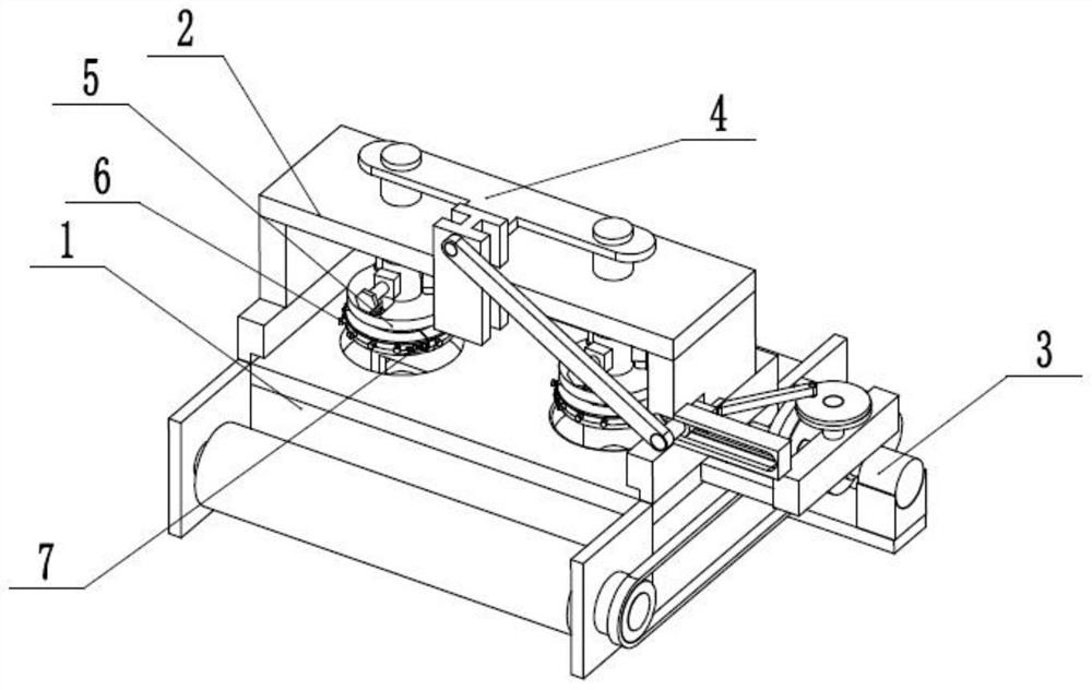
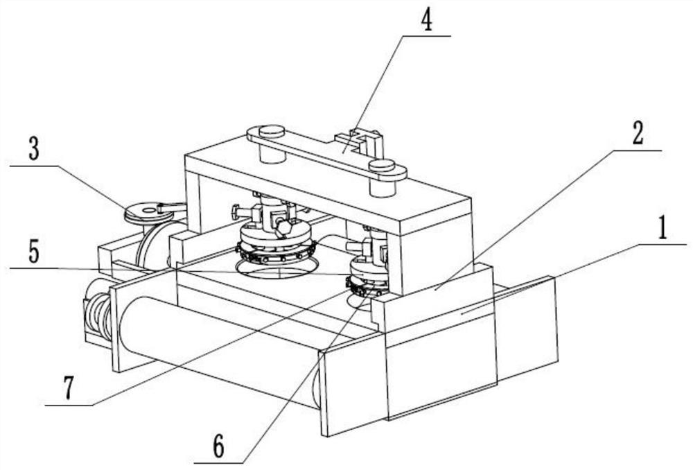
[0032] Such as Figure 1 to Figure 13 As shown, a bra processing device includes a processing fixed base 1, an upper fixed table 2, a combined driver 3, a cutting push seat 4, two bra size adjusting arc seats 5, an arc combined adjusting cutting edge 6 and a connecting spring cutting Blade 7, the upper fixed table 2 is fixedly connected to the upper end of the processing fixed base 1, the combined driver 3 is rotatably connected in the processing fixed base 1, and the cutting propulsion seat 4 is hinged with the combined driver 3 and is longitudinally slidably connected to the upper end of the processing fixed base 1. In the fixed table 2, two bra size adjustment arc seats 5 are slidingly connected to the cutting propulsion seat 4 through spherical grooves, and the arc combination adjustment cutting edge 6 is fixedly connected to the bra size adjustment arc seat 5, and the arc combination adjustment cutting edge 6 The upper fixed connection joins the spring cutting edge 7. Pu...
specific Embodiment approach 2
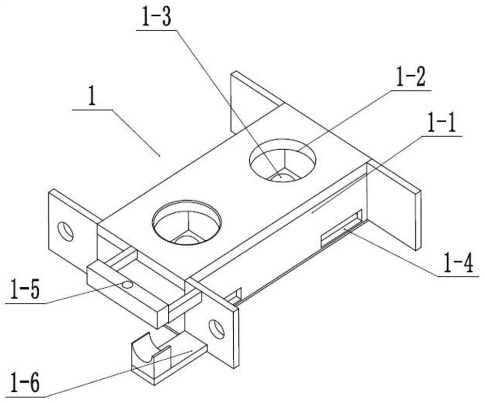
[0033] Such as Figure 1 to Figure 13 As shown, this embodiment will further explain Embodiment 1. The processing and fixing base 1 includes a processing box seat 1-1, two processing round holes 1-2, two spherical bases 1-3, two recycling Groove 1-4, extension fixing seat 1-5 and motor fixing seat 1-6, two processing round holes 1-2 are connected and arranged on the upper end of processing box seat 1-1, and two spherical bases 1-3 are fixedly connected In the processing box base 1-1, the two recovery grooves 1-4 are connected and arranged at the rear end of the processing box base 1-1, and the extension fixing seat 1-5 and the motor fixing base 1-6 are fixedly connected to the processing box base 1-1 left end. Place the cloth roll and the recovery roll to be cut at the drive unwinding roller 3-4 and the receiving roller 3-5. Make cloth pass through the upper end of processing box seat 1-1 after two cloth limit chute 2-2 carry out the limit.
specific Embodiment approach 3
[0034] Such as Figure 1 to Figure 13 As shown, this embodiment will further explain the second embodiment. The upper fixed platform 2 includes two cloth limit slides 2-1, two cloth limit chutes 2-2, and a concave knocking platform 2-2. 3. Drive sliding seat 2-4, longitudinal T-shaped chute 2-5 and two longitudinal sliding holes 2-6, and two cloth limit sliding seats 2-1 are respectively fixedly connected to the left and right sides of the upper end of processing box seat 1-1 On both sides, the cloth limit slide 2-1 is provided with the cloth limit chute 2-2 that runs through front and back, and the concave knocking platform 2-3 is fixedly connected to the upper ends of the two cloth limit slides 2-1, and the drive Sliding seat 2-4 is fixedly connected to the left end of concave-shaped knocking platform 2-3, and longitudinal T-shaped chute 2-5 and two longitudinal slide holes 2-6 are all vertically arranged on concave-shaped knocking platform 2-3. The longitudinal T-shaped ch...
PUM
 Abstract
Description
Claims
Application Information
 - R&D
- Intellectual Property
- Life Sciences
- Materials
- Tech Scout
- Unparalleled Data Quality
- Higher Quality Content
- 60% Fewer Hallucinations
Browse by: Latest US Patents, China's latest patents, Technical Efficacy Thesaurus, Application Domain, Technology Topic, Popular Technical Reports.
© 2025 PatSnap. All rights reserved.Legal|Privacy policy|Modern Slavery Act Transparency Statement|Sitemap|About US| Contact US: help@patsnap.com