Bed guardrail supporting structure and bed guardrail
A technology for supporting structures and guardrails, applied in the field of bed guardrails, can solve the problems of poor stability and firmness of bed guardrails, prone to loosening, poor versatility, etc., achieve good stability and firm reliability, improve the scope of application, and improve safety. Effect
- Summary
- Abstract
- Description
- Claims
- Application Information
AI Technical Summary
Problems solved by technology
Method used
Image
Examples
Embodiment 1
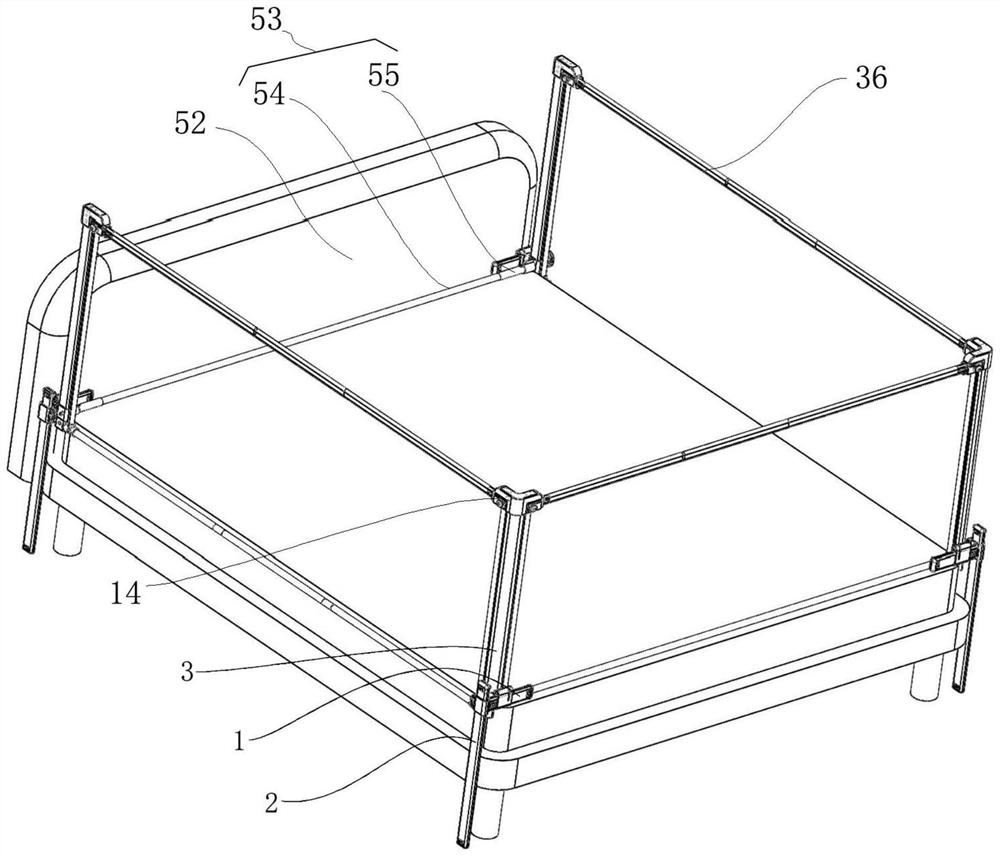
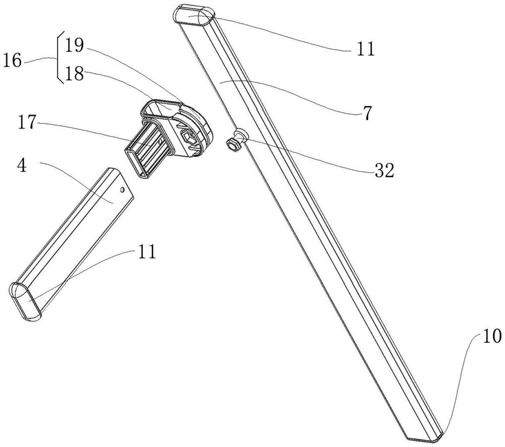
[0043] Such as Figure 1~7 As shown, it includes: a horizontal adjustment part 1, a vertical adjustment part 2 and a guardrail bracket part 3; the horizontal adjustment part 1 includes a horizontal strut 4 and a transverse sleeve device 5, the transverse strut 4 can be movably sleeved on the transverse sleeve device 5, and the transverse support rod 4 can be fixed in position by the transverse socketing device 5, specifically, such as figure 2 As shown, the horizontal support rod 4 and the following vertical support rod 7 are rectangular aluminum alloy rods with rounded edges;
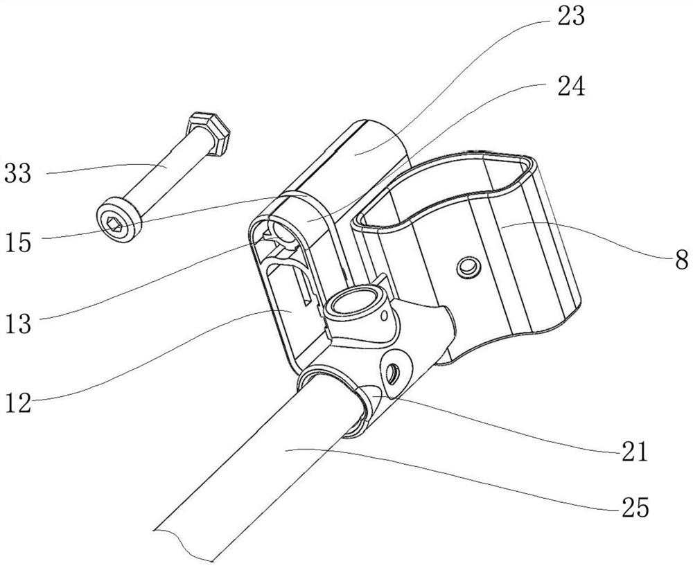
[0044] Moreover, in this embodiment, the transverse sleeve device 5 includes a transverse sleeve 12 and a first fixing device 13 arranged on the side of the transverse sleeve 12, and a fastening device 13 is inserted between the first section 23 and the second section 24. Specifically, the transverse sleeve device 5 simultaneously plays the role of supporting and fixing the transverse strut 4, after the t...
Embodiment 2
[0059] Compared with embodiment 1, embodiment 2 is on the basis of embodiment 1. Both the horizontal socketing device 5 and the vertical socketing device 6 adopt a casing structure with fastening screws on the side, and the horizontal support rod 4 After adjusting the vertical support rod 7 to a proper position, the horizontal support rod 4 and the vertical support rod 7 sleeved in the casing can be tightened and fixed directly by fastening screws. This fixing method is simpler and more convenient.
Embodiment 3
[0061] Such as Figure 4 , Figure 5 As shown, compared to Embodiment 1, in this embodiment, the bottom of the vertical rod bottom cover 22 is provided with a concave rounded corner 28, and the concave rounded corner 28 abuts the corner of the side edge of the mattress, that is, two adjacent surfaces The concave rounded corner 28 is formed, in which the first surface 30 abuts the upper surface of the mattress or the upper surface of the bed edge, wherein the second surface 31 abuts the side of the mattress or the bed edge, and the second surface 31 may be There will also be a little gap. The first sleeve 26 is arranged on the rounded side wall 29 of the concave rounded corner 28 where the second surface 31 is located. The first sleeve 26 and the first pull rod 27 are arranged close to the side wall of the mattress; In the above structural design, the second sleeve 21 and the second tie rod 25 are arranged on the upper part of the mattress, and the first tie rod 27 and the first ...
PUM
 Abstract
Description
Claims
Application Information
 - R&D
- Intellectual Property
- Life Sciences
- Materials
- Tech Scout
- Unparalleled Data Quality
- Higher Quality Content
- 60% Fewer Hallucinations
Browse by: Latest US Patents, China's latest patents, Technical Efficacy Thesaurus, Application Domain, Technology Topic, Popular Technical Reports.
© 2025 PatSnap. All rights reserved.Legal|Privacy policy|Modern Slavery Act Transparency Statement|Sitemap|About US| Contact US: help@patsnap.com


