
Flushing system for improving cleanliness of hydraulic pipeline

A technology for flushing systems and hydraulic pipelines, applied in the field of flushing systems, can solve the problems of unguaranteed cleaning quality and single cleaning method of flushing equipment, and achieve the effect of avoiding substandard cleanliness and avoiding single cleaning method.

Pending Publication Date: 2020-09-18
广州嘉诺工业技术有限公司
View PDF4 Cites 0 Cited by
  • Summary
  • Abstract
  • Description
  • Claims
  • Application Information

AI Technical Summary

Problems solved by technology

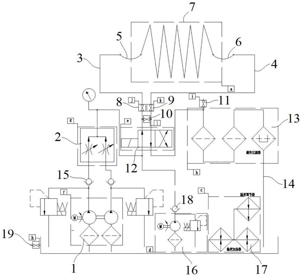
[0003] The purpose of the present invention is to provide a flushing system for improving the cleanliness of hydraulic pipelines, which is used to solve the technical problems in the prior art that the flushing equipment has a single cleaning method and the cleaning quality cannot be guaranteed

Method used


Image

  • Flushing system for improving cleanliness of hydraulic pipeline

Examples


Embodiment Construction

[0021] The specific implementation manners of the present invention will be further described in detail below in conjunction with the accompanying drawings and embodiments. The following examples are used to illustrate the present invention, but are not intended to limit the scope of the present invention.

[0022] Such as figure 1 As shown, a flushing system (hereinafter referred to as the flushing system) for improving the cleanliness of hydraulic pipelines is a preferred embodiment of the present invention. The flushing system includes a liquid storage tank, a liquid supply device, a reversing valve 12, a first pipeline 3, a second pipeline 4, a filter device 13 and a closed-loop pipeline 14; the liquid storage tank, the liquid supply device, and the reversing valve 12. The filter device 13 is sequentially connected in series on the closed-loop pipeline 14; one end of the first pipeline 3 and the second pipeline 4 are both connected to the reversing valve 12, and the other...


PUM


Abstract

The invention relates to a flushing system for improving the cleanliness of a hydraulic pipeline. The flushing system comprises a liquid storage tank, a liquid supply device, a reversing valve, a first pipeline, a second pipeline, a filtering device and a closed-loop pipeline. The liquid storage tank, the liquid supply device, the reversing valve and the filtering device are sequentially connectedto the closed-loop pipeline in series. One end of the first pipeline and one end of the second pipeline are communicated with the reversing valve, and the other end of the first pipeline and the other end of the second pipeline are used for being communicated with the pipeline to be flushed. A first valve is arranged on the first pipeline, a second valve is arranged on the second pipeline, and athird pipeline is communicated between the first pipeline and the second pipeline. A third valve is arranged on the third pipeline. The third pipeline is used for performing short circuit on the pipeline to be flushed. A first detection point is arranged on the filtering device. A second detection point is arranged on the liquid storage tank. By the adoption of the flushing system, the situation of singular cleaning mode is avoided, the self-circulation cleaning of the flushing system is achieved, the cleaning effect can be mastered in time by operators, and the situation that cleanliness is not standard is avoided.

Description

technical field [0001] The invention relates to the technical field of hydraulic pipeline cleanliness, in particular to a flushing system for improving hydraulic pipeline cleanliness. Background technique [0002] Pipeline transportation is a common transportation method in daily life. For some fields that require high precision, pipeline transportation needs to have a high degree of cleanliness. In order to improve the cleanliness of pipeline transportation, most of the existing technologies need the help of special The cleaning equipment flushes the inner wall of the pipeline, but the existing cleaning equipment has a single cleaning method and function, and there is no guarantee whether the cleanliness of the pipeline after cleaning meets the requirements. Contents of the invention [0003] The purpose of the present invention is to provide a flushing system for improving the cleanliness of hydraulic pipelines, which is used to solve the technical problems in the prior ...

Claims


Application Information

Patent Timeline
IPC IPC(8): B08B9/032B08B13/00C02F1/48
CPCB08B9/0325B08B13/00C02F1/48
Inventor 蔡国平傅建华
Owner 广州嘉诺工业技术有限公司
Learn More