Water-turbine generator set tight bushing disassembly device and disassembly method thereof

A technology of generator set and disassembly device, applied in the direction of hand-held tools, manufacturing tools, etc., can solve the problems of affecting the sealing effect, jamming of the casing and the main shaft, damage to the bushing, etc.

Pending Publication Date: 2020-09-18
HUBEI QINGJIANG HYDROPOWER DEV
View PDF1 Cites 1 Cited by
  • Summary
  • Abstract
  • Description
  • Claims
  • Application Information

AI Technical Summary

Problems solved by technology

[0004] The main purpose of the present invention is to provide a tight bushing dismantling device and its dismantling method for a hydraulic generator set, which solves the problem of the casing and main shaft being stuck after the long-term operatio

Method used


Image

  • Water-turbine generator set tight bushing disassembly device and disassembly method thereof
  • Water-turbine generator set tight bushing disassembly device and disassembly method thereof
  • Water-turbine generator set tight bushing disassembly device and disassembly method thereof

Examples


Embodiment 1

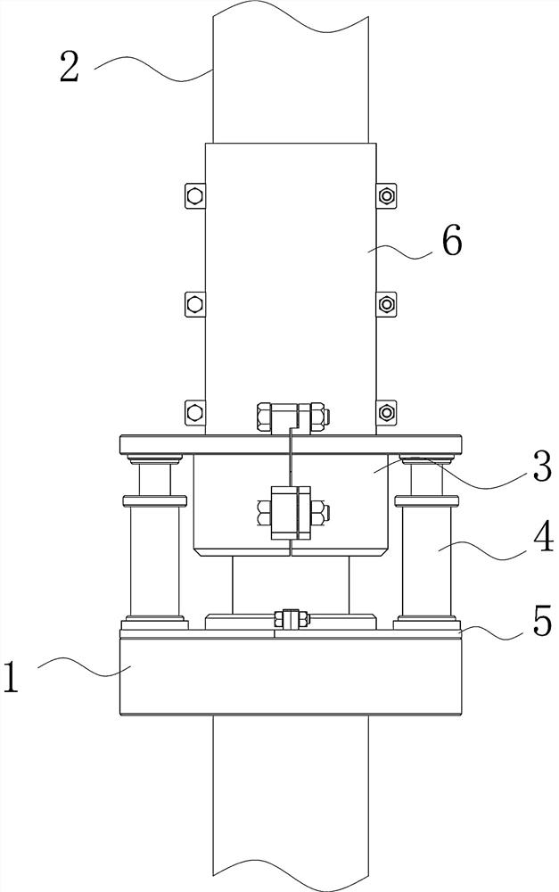
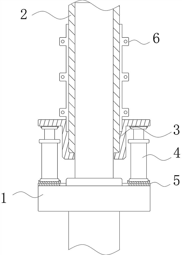
[0042] like Figure 1~14 As shown in the figure, a tight bushing removal device for a hydroelectric generator set includes a top sleeve 3, the top sleeve 3 includes two semicircular sleeve plates, and the bottom of the two semicircular sleeve plates is sleeved on the end of the sleeve 2 , the upper outer circumference of the cover plate is provided with a protruding disk body, and a bottom plate 5 is provided under the top cover 3. The hydraulic cylinder 4, the piston end of the hydraulic cylinder 4 leans against the disc body at the upper end of the top sleeve 3 . With this structure, the hydraulic cylinder 4 is used to push the top sleeve 3, and the top sleeve 3 drives the bush to rise to achieve the purpose of disassembly, and the lower part of the top sleeve 3 wraps the end of the bush 2 to protect the end of the bush 2 from pressure. The utility model has the advantages of convenient disassembly, improved work efficiency, simple structure, convenient use, and is suitable...

Embodiment 2

[0052] Further illustrate in conjunction with embodiment 1, as Figure 1~14 Shown: The method includes:

[0053] Put the first circular plate 501 and the second circular plate 502 on the boss position of the main shaft 1 of the air supply valve and splice them into an annular bottom plate 5 , and use a spirit level to adjust the balance of the bottom plate 5 .

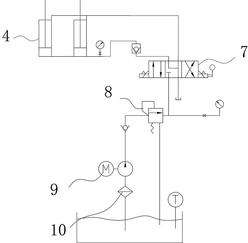
[0054] The hydraulic cylinder 4 is placed in the placement groove 503 of the bottom plate 5 , and the hydraulic pipe is used to communicate with the electromagnetic reversing valve 7 , and the electromagnetic reversing valve 7 communicates with the hydraulic pump 9 .

[0055] Regulate the electromagnetic reversing valve 7 and the hydraulic pump 9 to make the two hydraulic cylinders 4 retract to the bottom and keep the piston ends of the two hydraulic cylinders 4 on the same plane.

[0056] The first set plate 301 and the second set plate 302 are set on the end of the bushing 2, the bosses at the bottom of the first se...


PUM


Abstract

The invention provides a water-turbine generator set tight bushing disassembly device and a disassembly method thereof. An ejection sleeve comprises two semi-circular sleeve plates, wherein the lowerportions of the two semi-circular sleeve plates sleeve the end of a bushing, the outer circumferential rings of the upper ends of the sleeve plates are provided with protruding disk bodies, a bottom plate is provided below the ejection sleeve, the bottom plate is arranged on a main shaft boss of a gulp valve, at least two hydraulic cylinders are arranged between the bottom plate and the ejection sleeve, the hydraulic cylinder piston ends abut against the disk bodies at the upper end of the ejection sleeve, the sleeve plates comprise a first sleeve plate and a second sleeve plate, the first sleeve plate and the second sleeve plate are rotationally symmetric along the axis, a plurality of lug plates are arranged on the first sleeve plate, the two sleeve plates penetrate through the lug plates through double-head nuts to form the ejection sleeve, the lug plates are provided with positioning structures, through improvement of a bushing disassembly method, a set gulp valve sleeve can be smoothly disassembled, sealing can be smoothly replaced, damage to equipment caused by an original method is reduced, the sealing effect of the gulp valve is strengthened, the working efficiency is improved, the structure is simple, use is convenient, and the device is suitable for popularization and use.

Description

technical field [0001] The invention relates to the field of dismantling tight bushings of hydraulic generator sets, in particular to a device for removing tight bushings of hydraulic generator sets and a dismantling method thereof. Background technique [0002] The sealing ring of the air supply valve of the hydro-generator set needs to be replaced regularly, and the main shaft bushing of the air supply valve needs to be disassembled when replacing the seal. After long-term operation of the unit, the bushing and the main shaft are stuck. In the absence of special tools, tools such as pipe wrench and hand hammer are usually used. It is difficult or impossible to disassemble, and the bushing will be damaged and deformed during the disassembly process, affecting Sealing effect. [0003] Chinese patent CN 205950640 U "A device for removing oil pump bushings" discloses a device for removing oil pump bushes, including a clamp, a first collar and a second collar. The pull claw i...

Claims


Application Information

Patent Timeline
IPC IPC(8): B25B27/02
CPCB25B27/026
Inventor 张晋境张琼董峰王帅祝迪孔祥宇
Owner HUBEI QINGJIANG HYDROPOWER DEV
Why Eureka
Try Eureka