
Gearbox used for rail transit vehicle

A technology for rail transit vehicles and gearboxes, which is applied in the field of gearboxes for rail transit vehicles. It can solve problems such as difficult installation and high chassis, and achieve the effects of convenient installation and maintenance, improved stability, and increased span

Inactive Publication Date: 2016-03-23
南京高精轨道交通设备有限公司
View PDF7 Cites 5 Cited by
  • Summary
  • Abstract
  • Description
  • Claims
  • Application Information

AI Technical Summary

Problems solved by technology

[0003] The purpose of the present invention is to provide a gear box for rail transit vehicles in view of the technical problems such as installation difficulties and high chassis of the current basic structure of rail gearboxes, and the lubrication problems that may be caused by structural improvements.

Method used


Image

  • Gearbox used for rail transit vehicle
  • Gearbox used for rail transit vehicle
  • Gearbox used for rail transit vehicle

Examples


Embodiment Construction

[0022] The accompanying drawings disclose the specific structures of the embodiments of the present invention without limitation, and the technical solutions of the present invention will be described in detail below in conjunction with the accompanying drawings.

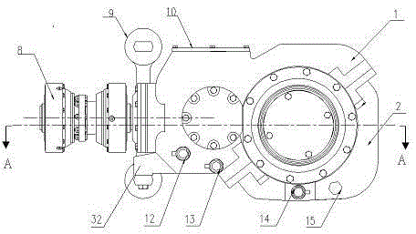
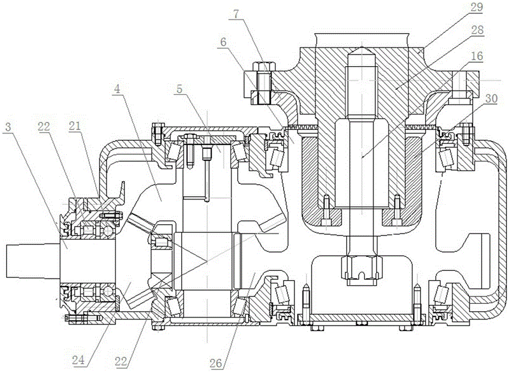
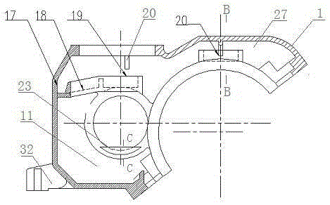
[0023] Depend on figure 1 It can be seen that the gear box of a rail transit vehicle includes an upper box body 1 and a lower box body 2. The upper box body 1 is provided with a boom mounting seat 32, and the lower end of the boom 9 is connected with the boom mounting seat 32. The upper box body 1 and the lower box body The joint surface of the body 2 passes through the center line of the output shaft 6, and the included angle with the horizontal direction is 38 degrees. There is an upper oil pool 11 under the upper box body 1, and a lower oil pool and an upper oil pool 11 under the lower box body 2. An oil discharge hole 13 is provided, an oil discharge hole 14 is provided in the lower oil tank, an oil filling hole...


PUM


Abstract

The invention relates to a gearbox used for a rail transit vehicle. Center lines of an input shaft and an output shaft of the gearbox are perpendicular to each other; a middle gear shaft which is parallel to the output shaft is arranged between the input shaft and the output shaft; the input shaft is engaged with a middle bevel gear of the middle gear shaft by virtue of a spiral bevel gear; supporting points at the two ends of the output shaft are hollow shafts; an output big gear is arranged on the output shaft; the middle gear shaft is engaged with the output large gear on the output shaft; an output flange plate is positioned at the output side of the output shaft; a jointed surface of the output flange plate and the output shaft is end surface teeth which are matched with each other; and the output flange plate passes through a central connecting bolt, so that end surface teeth of the jointed surface are engaged with each other. A mounting hole which is in butt joint with the output flange plate is mounted in the central axis of the output shaft, and the central connecting bolt is assembled in the mounting hole; the input shaft is supported on an upper box body by virtue of one four-point ball bearing and two cylindrical roller bearings in a input bearing base; and the two ends of each of the middle gear shaft and the output shaft are respectively supported on a box body by virtue of a bearing in the bearing base.

Description

technical field [0001] The invention relates to a gear box, in particular to a gear box for rail transit vehicles. Background technique [0002] With the continuous development of urban rail transit vehicles, the types of rail transit gearboxes are also increasing, especially the gearboxes for trams will have great development prospects in the future. However, the tram gearbox is in the development stage of localization. How to realize the light weight of the tram gearbox needs to be continuously strengthened; how to arrange the optimized gearbox structure needs to be analyzed in detail. For example, the early orbital gearboxes are usually installed in the middle of the transmission shaft, the transmission shaft passes through the gearbox, and the input shaft is parallel to the transmission shaft. The orbital gearbox with this structure is not only inconvenient to install, but also needs to occupy The higher installation space results in a higher chassis for the carriage. ...

Claims


Application Information

Patent Timeline
IPC IPC(8): F16H57/021F16H57/023F16H57/029F16H57/04
CPCF16H57/021F16H57/023F16H57/029F16H57/0409F16H2057/02043F16H2057/0235
Inventor 姜巨标何宏高曹启亮朱士元杨林
Owner 南京高精轨道交通设备有限公司
Learn More