Punching device used for folding stool machining

A technology of punching device and mounting plate, applied in fixed drilling machine and other directions, can solve the problems of difficult fixing of wood and complicated operation process, and achieve the effect of improving work efficiency

Active Publication Date: 2020-09-18
永康市捷灿工贸有限公司
View PDF9 Cites 9 Cited by
  • Summary
  • Abstract
  • Description
  • Claims
  • Application Information

AI Technical Summary

Problems solved by technology

[0004] In order to overcome the disadvantages of complex operation process and difficulty in fixing wood, the technical problem of the present invention is to provide a punching device for fixing wood with high work efficiency and simplified operation process.

Method used


Image

  • Punching device used for folding stool machining
  • Punching device used for folding stool machining
  • Punching device used for folding stool machining

Examples


Embodiment 1

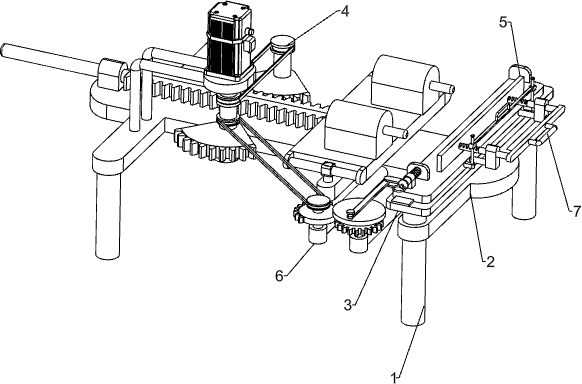
[0048] A kind of perforating device for maza processing, such as figure 1 As shown, it includes a base 1, a mounting plate 2, a slide rail plate 3, a punching mechanism 4, and a clamping mechanism 5. The bottom of the mounting plate 2 is provided with a base 1, and the upper right part of the mounting plate 2 is connected with a slide rail. Plate 3, the upper side of mounting plate 2 is connected with punching mechanism 4, and punching mechanism 4 is positioned at the left side of slide rail plate 3, and the upper side of slide rail plate 3 is slidably connected with clamping mechanism 5.

[0049] When the staff needs to punch holes in the wood for making Maza, the staff can pull the clamping mechanism 5 forward, place the wood on the clamping mechanism 5, and loosen the clamping mechanism 5, so as to clamp and fix the wood The purpose of starting the punching mechanism 4, the punching mechanism 4 moves to the right, and the wood is punched. After the operation, close the punc...

Embodiment 2

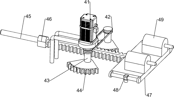
[0051] On the basis of Example 1, such as figure 2 As shown, the punching mechanism 4 includes a motor 41, a first transmission assembly 42, a first rotating shaft 43, a sector gear 44, a rack bar 45, a first sliding sleeve 46, a first sliding plate 47, a second sliding sleeve 48 and Hitting machine 49, the left side of the top of the mounting plate 2 is connected to the motor 41 through the mounting bracket, the front and rear sides of the top of the mounting plate 2 are rotatably connected to the first rotating shaft 43 through the bearing seat, the first rotating shaft 43 at the front and the output shaft of the motor 41 The first transmission assembly 42 is wound between the first rotating shafts 43, the sector gear 44 is connected to the lower part of the first rotating shaft 43, and the first sliding sleeve 46 is connected to the upper side of the left part of the mounting plate 2, and the inside of the first sliding sleeve 46 The rack bar 45 is slidingly connected, and...


PUM


Abstract

The invention relates to a punching device, in particular to a punching device used for folding stool machining. The punching device used for folding tool machining is capable of improving efficiency,simplifying operation process and fixing wood. According to the technical scheme, the punching device used for folding stool machining comprises bases, a sliding rail plate, a punching mechanism anda clamping mechanism; at least four bases are connected to the bottom of an installation plate; the sliding rail plate is connected to one side of the top of the installation plate; the punching mechanism is connected to the position, away from the side with the sliding rail plate, of the installation plate; and the clamping mechanism is connected to the top of the sliding rail plate in a slidingmanner. Due to the cooperation of a motor, a rotating shaft, a rack lever and a striking machine, the purpose of punching the wood is achieved, and efficiency is improved; and due to cooperation of apull ring rod, a spring, a baffle and a second sliding plate, the purpose of clamping and fixing the wood is achieved.

Description

technical field [0001] The invention relates to a punching device, in particular to a punching device for horse tie processing. Background technique [0002] Wood processing, using wood as raw material, is mainly processed by mechanical or chemical methods, and its products still maintain the basic characteristics of wood. Wood plays a great role in supporting human life. According to the different properties and characteristics of wood, people use them in different ways. [0003] This patent relates to a punching device for Maza processing. The traditional Maza processing punching method is to place the wood on the instrument, start the punching device, push the wood forward, and punch the wood, and then the staff continuously punches the wood. Replacement, this method has the disadvantages of low efficiency, complicated operation process, and difficult fixing of wood. Contents of the invention [0004] In order to overcome the disadvantages of complicated operation pro...

Claims


Application Information

Patent Timeline
Patent Type & Authority Applications(China)
IPC IPC(8): B27C3/04
CPCB27C3/04
Inventor 彭江安
Owner 永康市捷灿工贸有限公司
Why Eureka
Try Eureka