Construction method for pile-anchor support of spiral cage core anchor rod

A construction method and anchor pile technology, which is applied in excavation, sheet pile walls, foundation structure engineering, etc., can solve the problem of poor tensile capacity of anchor support, poor tensile performance of plain concrete, and ineffective anchor support. Meet the problems of engineering construction and achieve the effect of increasing the ultimate load, improving the pull-out resistance and increasing the strength

Active Publication Date: 2020-09-18
中建富林集团有限公司
View PDF6 Cites 4 Cited by
  • Summary
  • Abstract
  • Description
  • Claims
  • Application Information

AI Technical Summary

Benefits of technology

This technology allows for quicker assembly by adding an anchor rod made from synthetic resins or other materials like cement instead of traditional wood rods used in construction projects. It also uses a special type of material called capillary tube filled with water to help it harden properly when installed inside the borehole after being placed there. These improvements make the anchor's pulling out resistant more effectively than older methods such as steel bars alone.

Problems solved by technology

This patented technical problem addressed by this patents relates to improving the strength or durability of conventional bolts used during civil infrastructure works such as foundations that require strong supporting structures due to their size and weight.

Method used


Image

  • Construction method for pile-anchor support of spiral cage core anchor rod
  • Construction method for pile-anchor support of spiral cage core anchor rod
  • Construction method for pile-anchor support of spiral cage core anchor rod

Examples


Embodiment 1

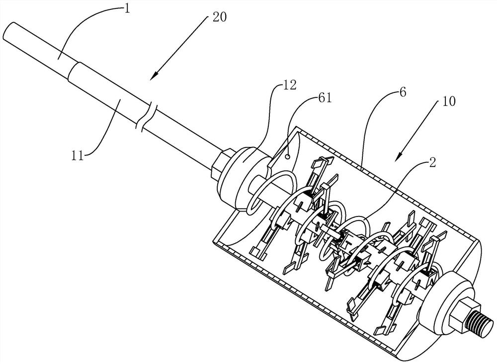
[0056] Embodiment 1: as figure 1 As shown, it is an anchor rod structure disclosed by the present invention, which includes a rod body 1, the rod body 1 has a free section 20 and an anchoring section 10, wherein the free section 20 of the rod body 1 is provided with an anti-corrosion structure 11, and the anchoring section 10 of the rod body 1 is sleeved There are spiral ribs 2 , and the outer cover of the anchoring section 10 of the rod body 1 is provided with a bladder 6 , and the bladder 6 is provided with a grouting port 61 .

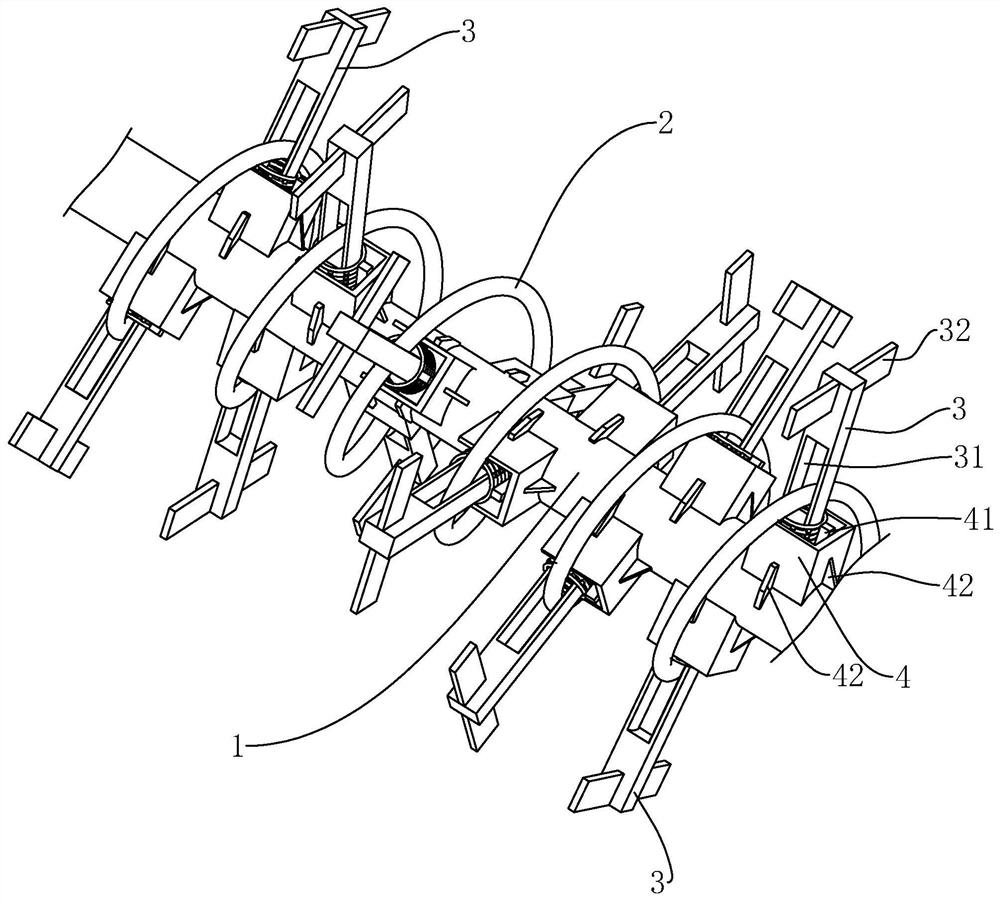
[0057] Such as figure 1 As shown, the spiral rib 2 and the rod body 1 are rotated around the axis of the rod body 1. The anchor section 10 is provided with two bearing bodies. The bearing body close to the free section 20 is named as the driving bearing body 12. Drive groove (not marked in the figure), one end of the spiral rib 2 is fixedly connected with the drive carrier 12, and the other end of the spiral rib 2 is in contact with another carrier...

Embodiment 2

[0062] Embodiment 2: be a kind of construction method of the spiral cage core bolt pile anchor support based on the anchor rod structure of embodiment 1, comprise the following steps:

[0063] S1. Construction preparations, including:

[0064] S1.1. Determine the construction plan, and prepare construction technical measures that meet the design specifications and process requirements;

[0065] S1.2. The technical research team goes deep into the construction site, investigates the actual situation on the site and the surrounding environment, consults the information, and reviews the drawings;

[0066] S1.3. Material preparation, labor preparation and tool preparation must meet the requirements.

[0067] S2. Determine the hole position, including:

[0068] S2.1. Carry out measurement and release according to the basic layout plan, record the process of setting out the wire; if the error of the hole position coordinates is within 50mm, determine the anchorage area, and detect...


PUM


Abstract

The invention relates to a construction method for a pile-anchor support of a spiral cage core anchor rod. The construction method comprises the following steps of S1, construction preparation; S2, hole position determination; S3, hole reaming and guiding; S4, pipe-following drilling; S5, anchorage section hole drilling; S6, anchor rod manufacturing; S7, anchor rod mounting; S8, supporting framework unfolding; S9, grouting; S10, anchor rod tensioning and locking; and S11, anchor sealing. By arranging a capsular bag capable of grouting and expanding and supporting frameworks matched with a spiral bar to unfold, a framework and bar cementing body with multiple framework structures is expanded and formed on an anchorage section of an anchor rod, and the diameter of the anchorage section is expanded. The framework and bar cementing body is high in structural strength, so that the drawing resistance of the anchor rod is improved greatly. Surrounding soil masses are compacted in the processes of unfolding the supporting frameworks and expanding the capsular bag. According to a correspondence principle of density of the soil masses, effective stress and shear strength, the strength of thesoil masses around the capsular bag is improved, so that the ultimate load of the anchor rod is improved greatly.

Description


Claims


Application Information

Patent Timeline
Owner 中建富林集团有限公司
Why Eureka
Try Eureka