Lifting frame for decoration

A lifting frame and connecting seat technology, which is applied in the field of lifting frames, can solve the problems of inconvenient entrance and exit due to large volume and inconvenient handling, and achieve the effect of avoiding multiple disassembly, facilitating handling and reducing volume.

Inactive Publication Date: 2020-09-18
胡勇强
View PDF0 Cites 0 Cited by
  • Summary
  • Abstract
  • Description
  • Claims
  • Application Information

AI Technical Summary

Problems solved by technology

[0003] The lifting frame for decoration is mainly used for the climbing work of the staff. The simplest lifting frame is a ladder. Nowadays, when carrying out indoor roof decoration work, the lifting frame with a support plane on the top is often used. The staff stands on the support plane However, the movable lifting frame used in the prior art is generally an integrated lifting frame fixed by welding and bolts. Because of its large size, it is not convenient to enter and exit from the door, so it is not easy to use in actual use. easy to carry

Method used


Image

  • Lifting frame for decoration
  • Lifting frame for decoration
  • Lifting frame for decoration

Examples


Embodiment 1

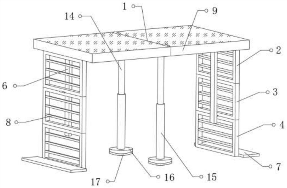
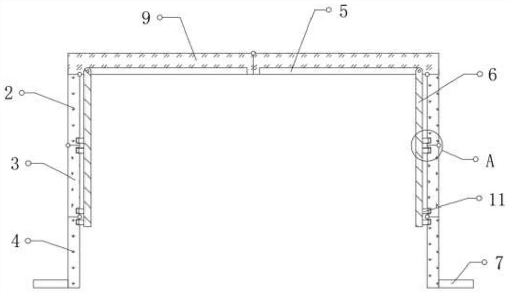
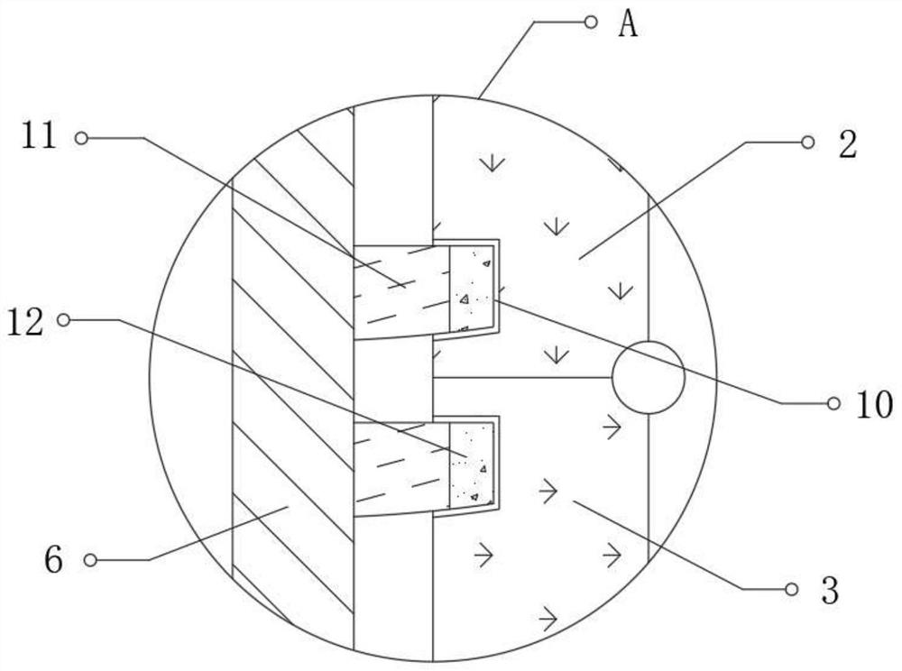
[0029] refer to Figure 1-5 , a lifting frame for decoration, including a support base 1, a support mechanism is provided on both sides of the bottom of the support base 1, and the support mechanism is provided with a first connection base 2 hinged with the support base 1, and the outer wall of the bottom of the first connection base 2 One side of the second connecting seat 3 is hinged, and one side of the outer wall of the bottom of the second connecting seat 3 is hinged with the third connecting seat 4, the axes of the first connecting seat 2, the second connecting seat 3 and the top of the third connecting seat 4 The positions are set at intervals, one side of the first connecting seat 2, the second connecting seat 3 and the third connecting seat 4 are provided with through grooves, and a plurality of pedals 8 are fixed between the inner walls of the two ends of the grooves, Both sides of the outer wall of the bottom of the support seat 1 are hinged with a positioning piece...

Embodiment 2

[0036] refer to Figure 1-4 and Figure 6 , a lifting frame for decoration, a connection hole is opened in the middle of the top of the bottom plate 16, and the bottom end of the outer wall of the support tube 15 is connected to the inner wall of the connection hole through bearing rotation, and the top of the outer wall of the support tube 15 is fixed with a ring array distribution The armrest 18, and the bottom of the rubber pad 17 is provided with a plurality of grooves 19.

[0037] During use, when the bottom plate 16 is screwed to the ground, the armrest 18 can be used to rotate the support cylinder 15 to press the bottom plate 16 vertically to squeeze the rubber pad 17 at the bottom, thereby enhancing the stability between the bottom of the bottom plate 16 and the ground, and further enhancing The actual use effect of the folding lifting frame.


PUM


Abstract

The invention belongs to the technical field of lifting frames, in particular to a lifting frame for decoration. Against the problem that an existing lifting frame for decoration is not convenient tocarry, the following scheme is proposed. According to the scheme, the lifting frame comprises a supporting seat, wherein supporting mechanisms are arranged at two sides of the bottom of the supportingseat, each supporting mechanism is provided with a first connecting seat hinged to the supporting seat, a second connecting seat is hinged to one side of the outer wall of the bottom of each first connecting seat, a third connecting seat is hinged to one side of the outer wall of the bottom of each second connecting seat, and axis positions at tops of the first connecting seats, the second connecting seats and the third connecting seats are distributed at intervals. According to the lifting frame, after usage is finished, locating pieces can be rotated and stored in storage grooves, the firstconnecting seats, the second connecting seats and the third connecting seats are sequentially rotated and stacked, and two supporting plates are stacked, so that the overall size of the lifting frameis reduced, the folding lifting frame is formed, the lifting frame is convenient to carry, and multiple times of dismantling is avoided.

Description

technical field [0001] The invention relates to the technical field of lifting frames, in particular to a lifting frame for decoration. Background technique [0002] Decoration, also known as decoration or decoration, refers to a complete set of construction plans and designs that are carried out in a certain area and range, including water and electricity construction, walls, floors, ceilings, landscapes, etc., based on certain design concepts and aesthetic rules. In the process of interior decoration, a large number of materials and auxiliary tools are often used. When decorating the roof or high places of the indoor environment, it is often necessary to use lifting frames for auxiliary operations. [0003] The lifting frame for decoration is mainly used for the climbing work of the staff. The simplest lifting frame is a ladder. Nowadays, when carrying out indoor roof decoration work, the lifting frame with a support plane on the top is often used. The staff stands on the ...

Claims


Application Information

Patent Timeline
Patent Type & Authority Applications(China)
IPC IPC(8): E04G1/22E04G1/30E04G1/34E04G5/00E04G5/02
CPCE04G1/22E04G1/30E04G1/34E04G5/00E04G5/02E04G5/025E04G2001/305
Inventor 胡勇强
Owner 胡勇强
Why Eureka
Try Eureka