Water channel structure and gas water heater water supply system with same
A technology of waterway structure and hot water pipeline, which is applied in the directions of fluid heaters, lighting and heating equipment, etc., can solve the problems of reducing the probability of one-way valve opening and not being fully guaranteed, and achieve the effect of flexible and fast movement and light weight.
- Summary
- Abstract
- Description
- Claims
- Application Information
AI Technical Summary
Problems solved by technology
Method used
Image
Examples
Embodiment 1
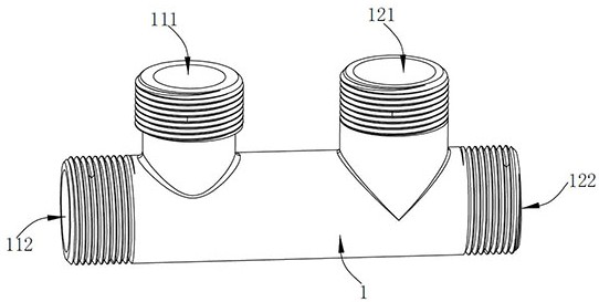
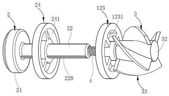
[0053] Such as Figure 1~7 As shown, the gas water heater water supply system of this preferred embodiment includes a waterway structure, a water heater 5, a cold water pipe 6, a hot water pipe 7, and at least one water point 8 connecting the cold water pipe 6 and the hot water pipe 7 at the same time. The water heater 5 is connected to the farthest water point 8 (ie, water tap), and the waterway structure includes a pipe body 1, a one-way valve assembly 2, and the like.
[0054] The inside of the pipe body 1 is divided into a hot water pipe 11, a cold water pipe 12, and an intermediate pipe 13 connecting the hot water pipe 11 and the cold water pipe 12. The hot water pipe 11 has a hot water inlet 111 and a hot water outlet 112 that are in fluid communication. The pipe 12 has a cold water inlet 121 and a cold water outlet 122 that are in fluid communication, and the axis of the cold water outlet 122 is parallel or coincident with the axis of the intermediate pipe 13. In this embo...
Embodiment 2
[0067] Such as Figure 8~12 As shown, the difference between Embodiment 2 and Embodiment 1 is:
[0068] 1. Such as Figure 8~10 As shown, the slot 221 of the connecting rod 22 is provided with a limiting member 222 capable of colliding with the second end of the screw 4, and when the second end of the screw 4 collides with the limiting member 222, the screw 4 can no longer be screwed in In the slot 221, it is ensured that the screw 4 can subsequently rotate in the opposite direction relative to the connecting rod 22. Otherwise, if the screw 4 is screwed into the slot 221 too deeply, the screw 4 and the connecting rod 22 will be locked. In this embodiment, the limiting member 222 is a spring, one end of the spring is connected with the bottom wall of the slot 221, and the other end faces the screw 4; the connecting rod 22 is provided with a first drain hole 226 in fluid communication with the slot 221, This prevents water from entering the slot 221 and affecting the movement of th...
Embodiment 3
[0080] Such as Figure 13~16 As shown, the difference between Embodiment 3 and Embodiment 2 is that the connecting rod 22 is designed in a separate body.
[0081] In this embodiment, the connecting rod 22 includes two connecting rods. One connecting rod is connected to the plug 21, and the other connecting rod is provided with a slot 221. For ease of description, the connecting rod connected to the plug 21 is The first connecting rod 223a, the connecting rod threadedly connected with the screw 4 is the second connecting rod 223b, the first connecting rod 223a and the second connecting rod 223b are insert-fitted and movable relative to the axial direction, the end of the first connecting rod 223a An insertion hole 224 is provided. The end of the second connecting rod 223b is provided with an insertion portion 225 that can be inserted into the insertion hole 224. The insertion portion 225 can move axially along the insertion hole 224, and the opening of the insertion hole 224 exten...
PUM
 Abstract
Description
Claims
Application Information
 - R&D
- Intellectual Property
- Life Sciences
- Materials
- Tech Scout
- Unparalleled Data Quality
- Higher Quality Content
- 60% Fewer Hallucinations
Browse by: Latest US Patents, China's latest patents, Technical Efficacy Thesaurus, Application Domain, Technology Topic, Popular Technical Reports.
© 2025 PatSnap. All rights reserved.Legal|Privacy policy|Modern Slavery Act Transparency Statement|Sitemap|About US| Contact US: help@patsnap.com


